A wavefolder with CV control over the amount of folds.
Me and Davey Graham were working on wavefolders at the same time independently. A few days after I posted this schematic for a simple wavefolder, Davey has extended upon it:
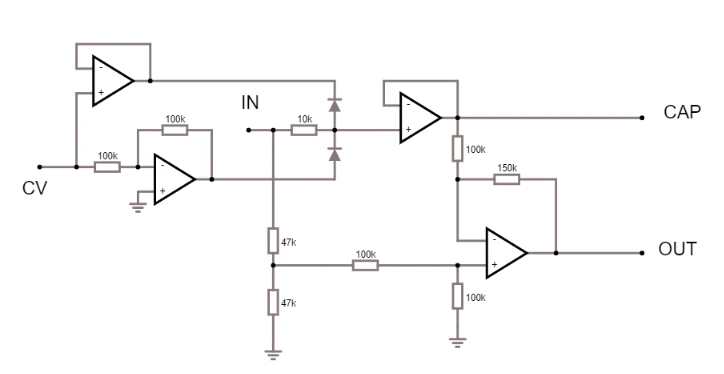
CAP is the input signal being clamped at +CV and -CV. I then subtract the original signal from the clamped signal to get a folded output.
Extending the clamping circuit with multiple limits and using the same principle as in Buchlas "Timbre Modulation" circuit where the input signal is split into multiple "deadbands" and then re-added and subtracted from each other to produce the folded output, we get the full circuit that was made by Davey Graham.
The deadbands are made using this diode structure, it can also be seen as a clamping circuit with variable clamping voltages:
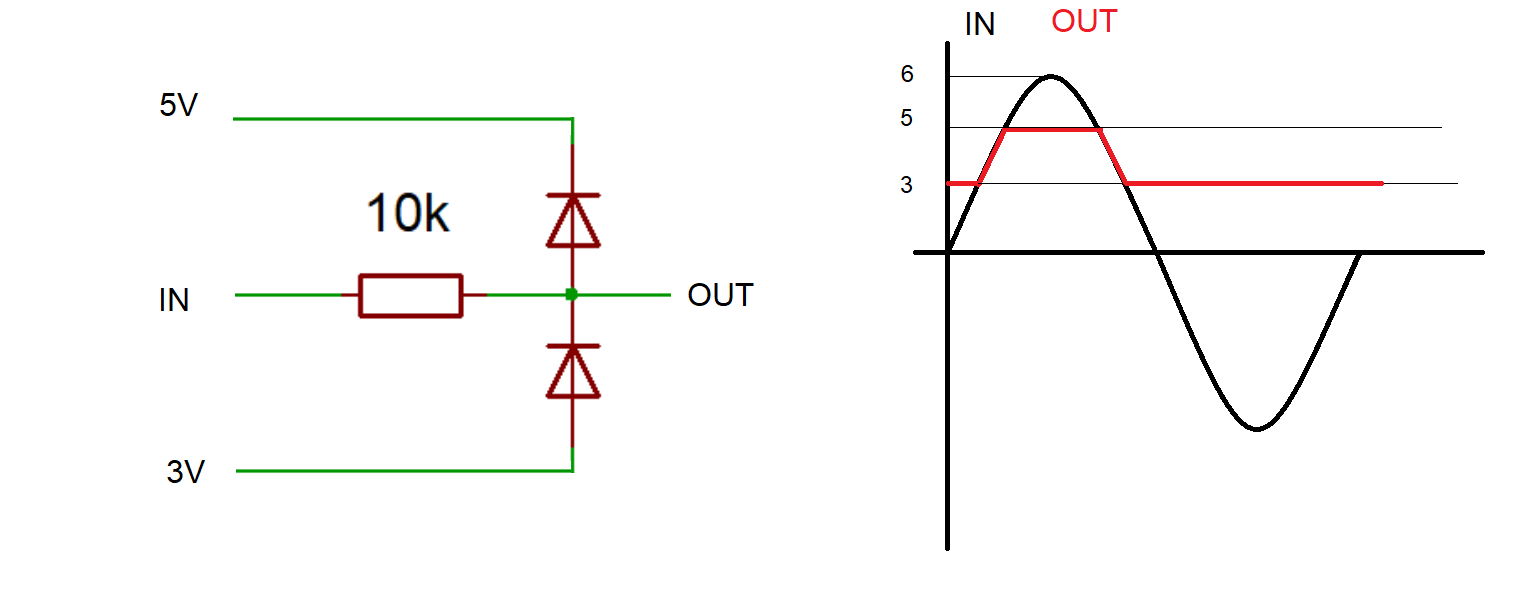
An example with the upper limit being 5V and the lower limit being 3V. The output of this circuit follows the input signal as long as it is within the upper and lower limits. The output never exceeds these limits (ignoring the diode drop).
The resistor chain and buffers are there to provide the upper and lower limits for the diodes.
How to get a folded output from deadbands?
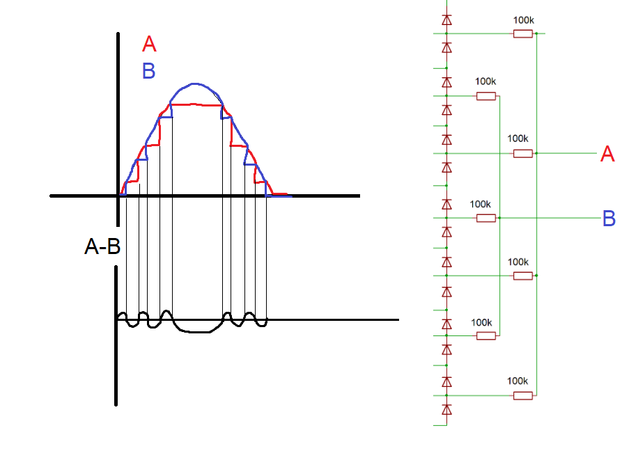
As in the Buchla circuit, every other band is summed together, resulting in two signals A and B (I did not draw the summing stages for simplicity) With no input, the bias voltages between the diodes sum up to zero volts, so with 0V in you get 0V out. OK. Boring.
With a sine input the signals A and B cross each other, and when B is subtracted from A, the resulting wave changes in polarity at every crossing, and we get folding.
How to add voltage control?
To get a fold, the input voltage needs to cross either the upper or lower limit of the clamping circuit, so the amount of folds depends on the amplitude and how many limits it is crossing. Using a VCA with a high gain gives control over the amplitude and thus the amount of folds. The output of the VCA is also directly fed to the "VCA" output, since you can never have enough VCAs.