10 KiB
Build Guide
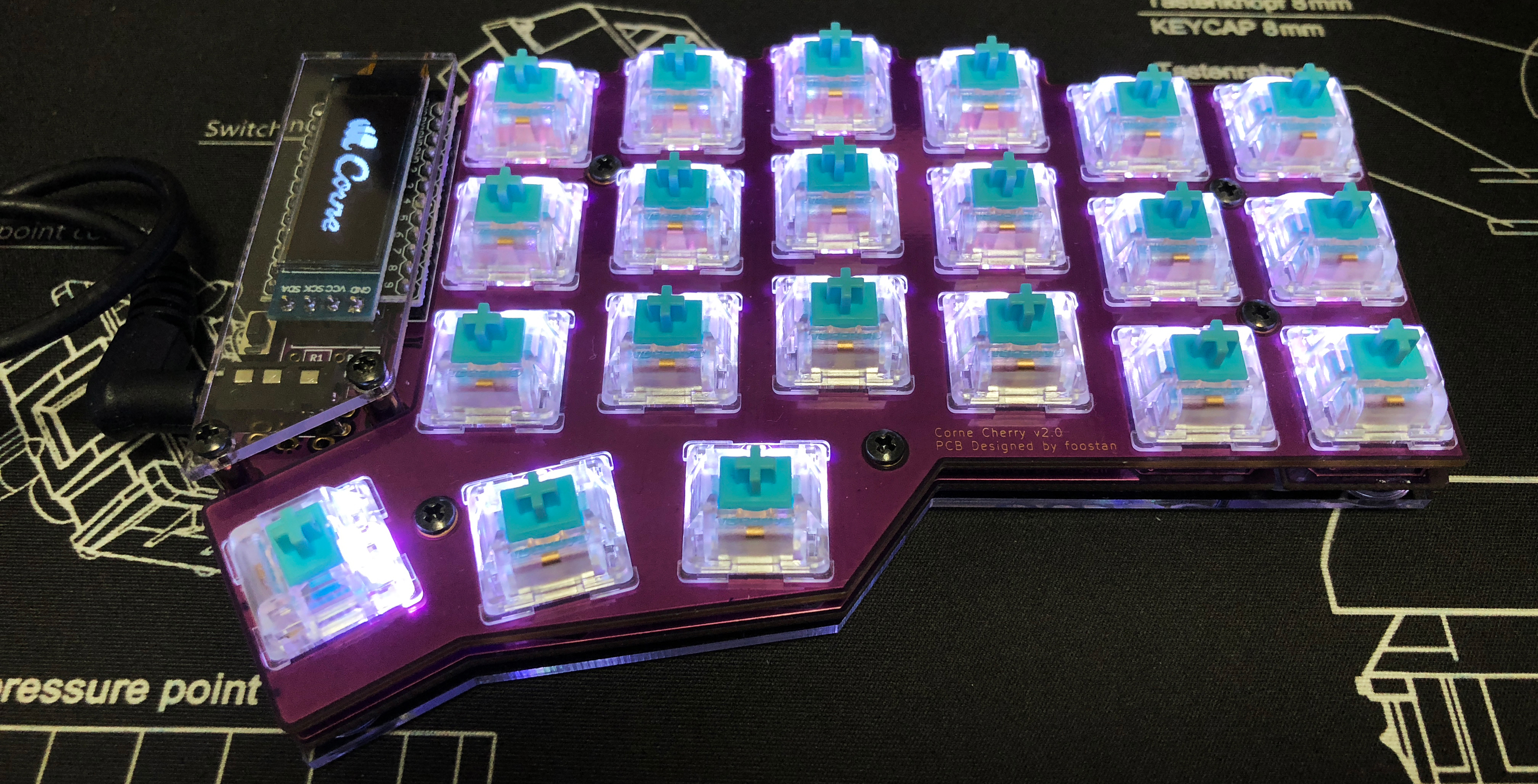
This is the build guide for Corne Cherry v2. Click here for the Corne Cherry v3 build guide.
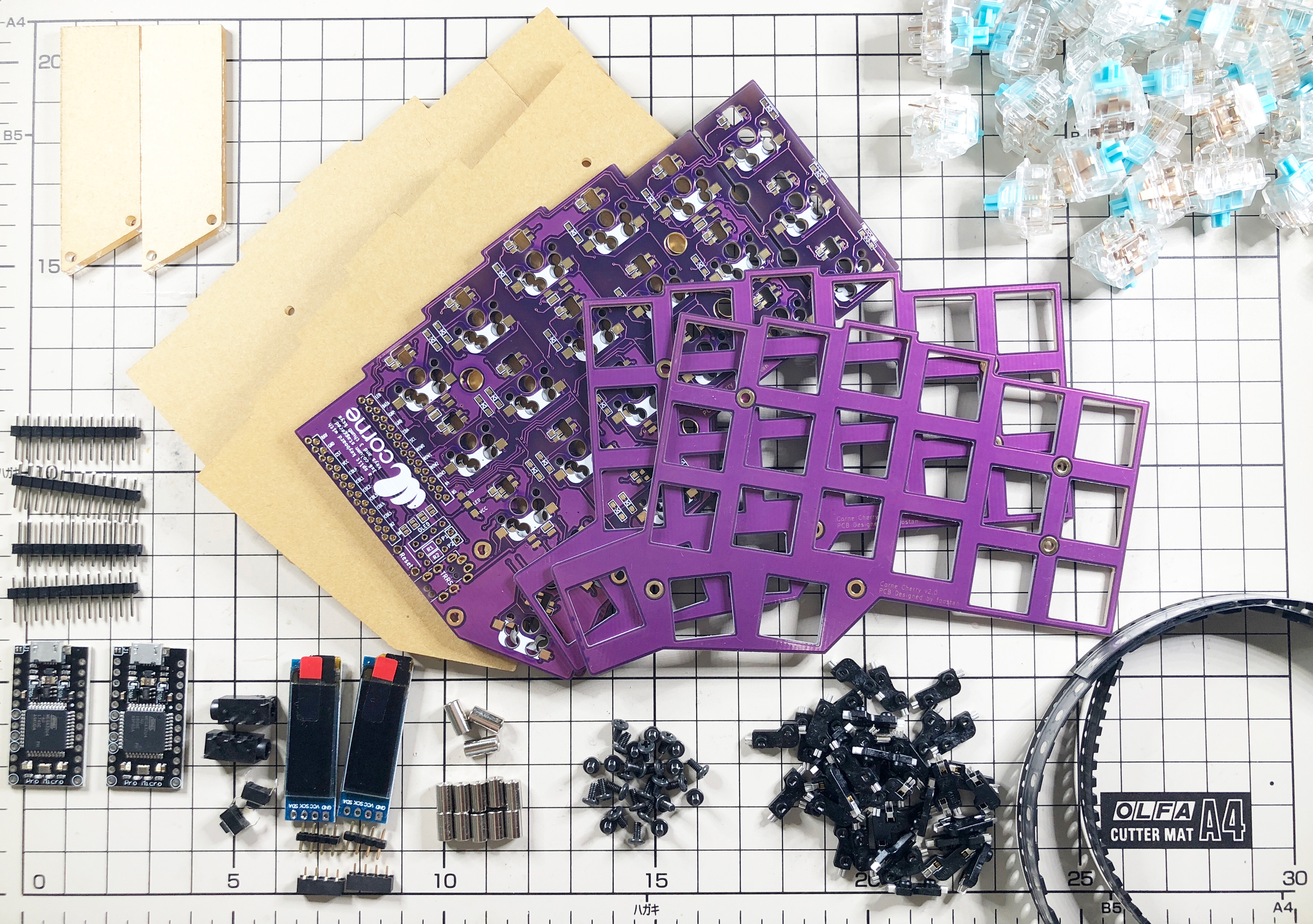
Parts
Required
| Name | Count | Remarks |
|---|---|---|
| PCB | 2 sheets | |
| Top plate | 2 sheets | |
| Bottom plate | 2 sheets | PCB type and acrylic type can be selected |
| ProMicro protective plate | 2 sheets | |
| ProMicro | 2 sheets | |
| TRRS jack | 2 | |
| Tact switch | 2 | |
| Diodes | 42 | Only chip parts |
| Kailh PCB Sockets | 42 | |
| Key switches | 42 | Only compatible with CherryMX |
| Keycaps | 42 pcs | 1u 40 pcs, 1.5u 2 pcs |
| OLED module | 2 sheets | |
| 4 pin headers | 2 | |
| 4 pin sockets | 2 | |
| Spacer M2 7.5mm | 10 pieces | |
| Spacer M2 9mm | 4 pieces | |
| Screw M2 4mm | 28 screws | |
| Cushion rubber | 8 pieces | |
| TRS (3-pole) cable | 1 | TRRS (4-pole) cable is also acceptable |
| Micro USB cable | 1 |
Optional
| Name | Count | Remarks |
|---|---|---|
| SK6812MINI | 54 pcs | Upward mounting 42 pcs, Downward mounting 12 pcs |
Advance preparation
If you build the firmware yourself,
it takes time to prepare the environment,
so it is recommended to start first.
See https://github.com/foostan/crkbd/blob/master/doc/firmware_en.md
for more information.
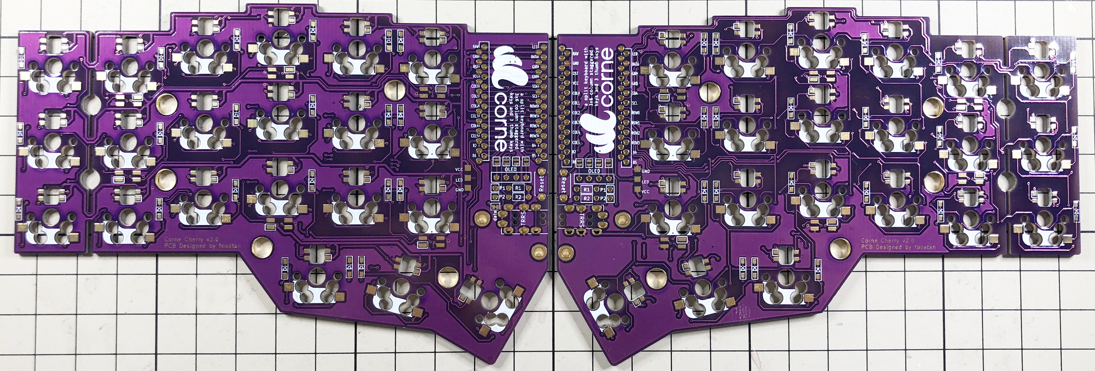
Implementation
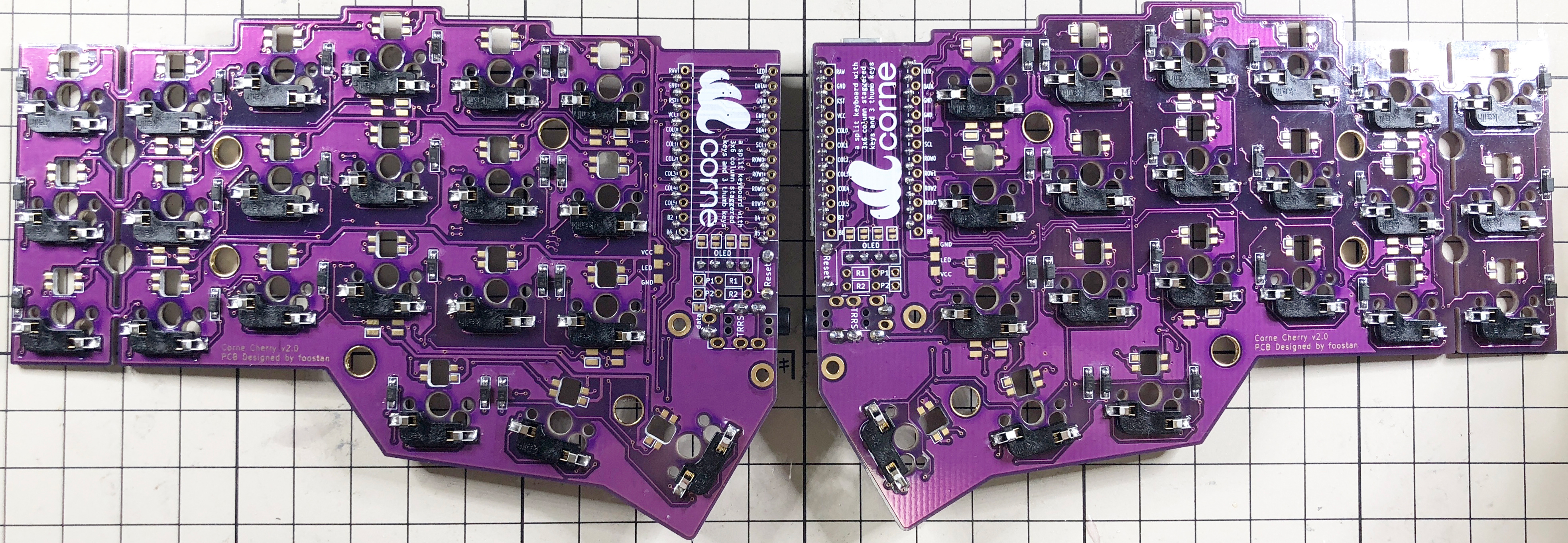
The PCB is reversible, so first decide which one to use, left or right.
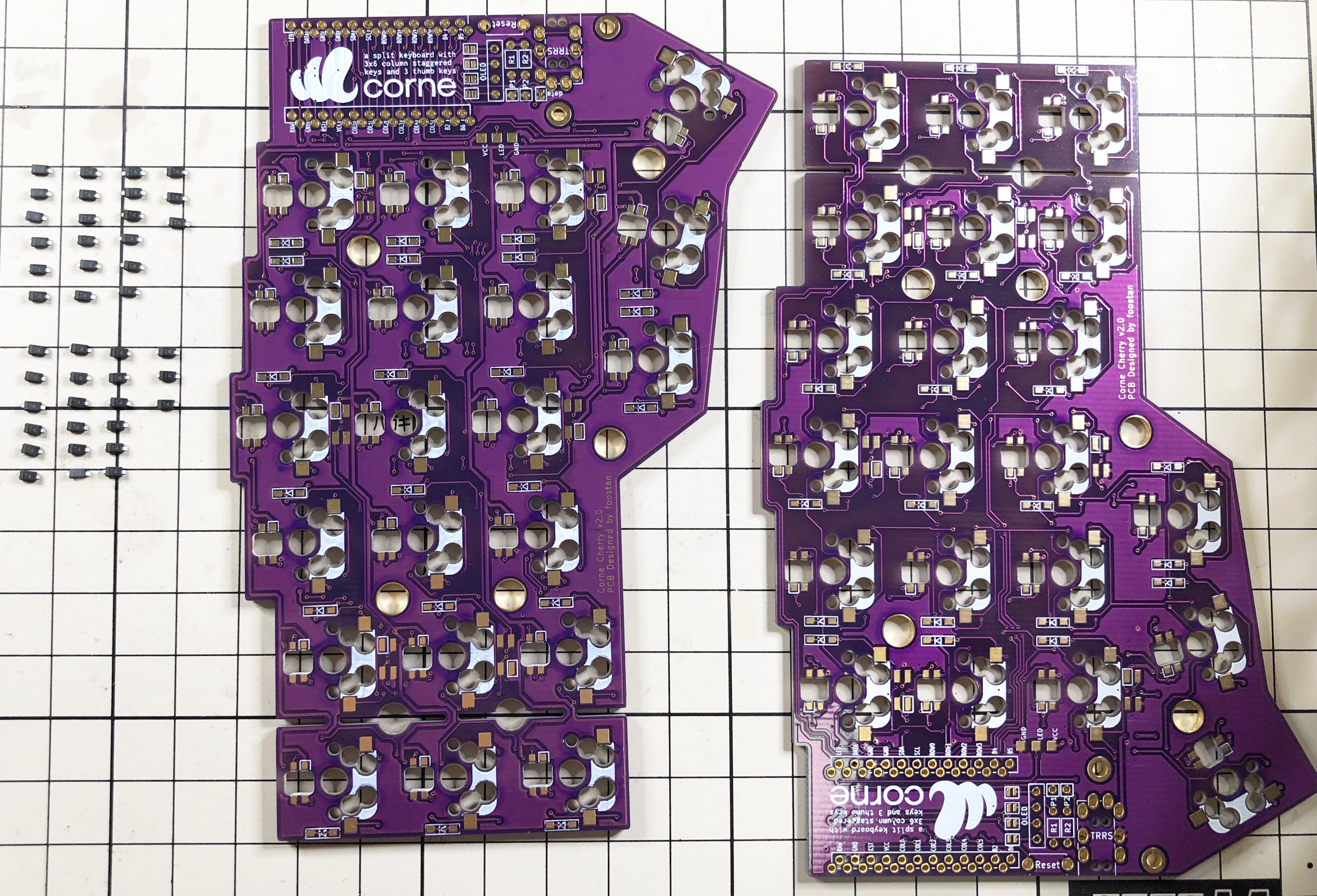
Diodes
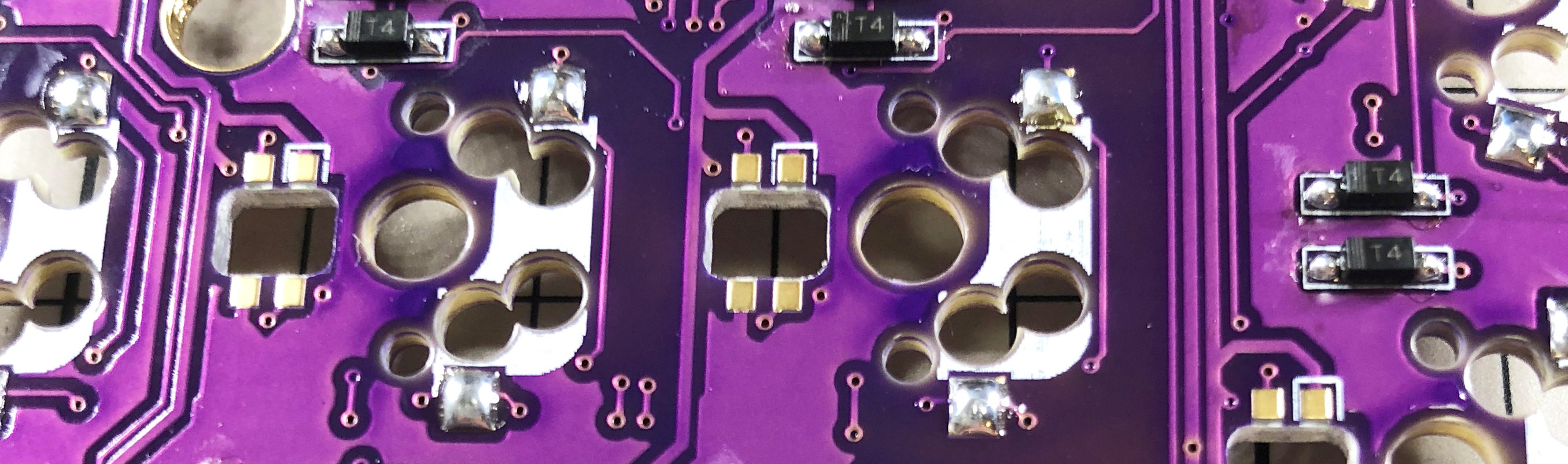
Solder the diode of the chip part. You can attach it to either side, but in this build guide, we will attach it to the back side. When using Tilting / Tenting plate, be sure to attach it to the back side __.
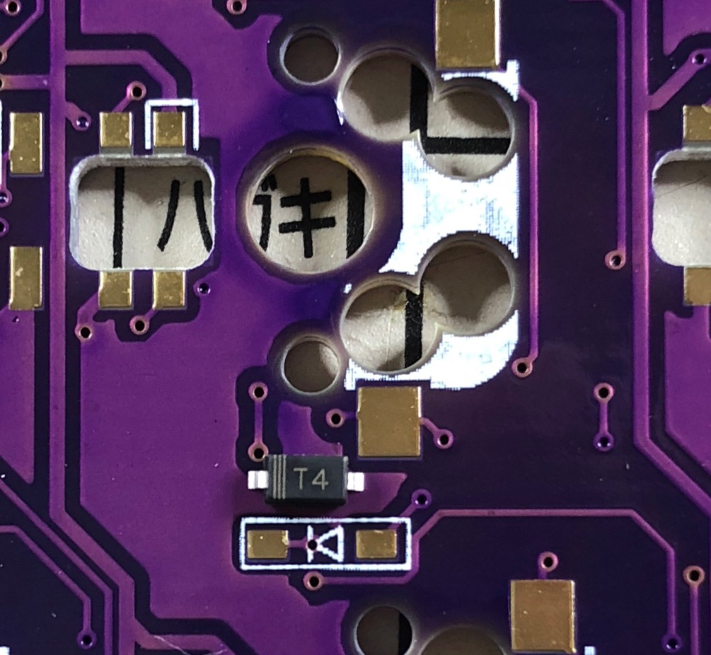
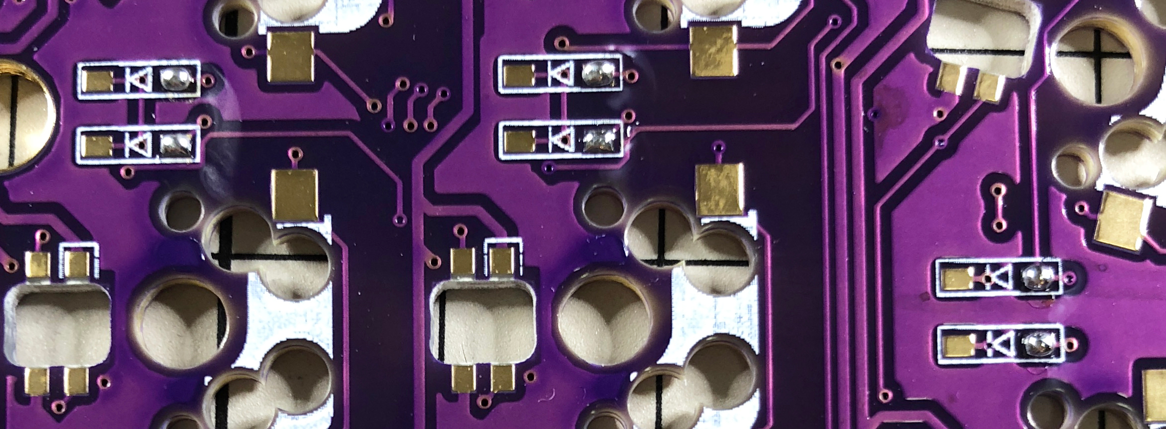
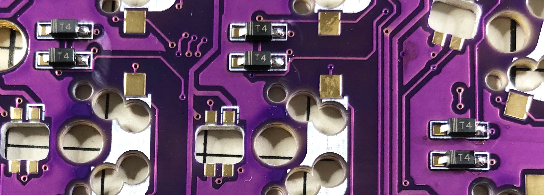
Since the chip parts are very small, it is easier to work with tweezers and counter-acting tweezers. **The diode is installed in a fixed direction **, so if you arrange the diode in the same row and row as shown in the photo below, it will proceed smoothly.
The orientation of the diode is as follows: Install so that the "|||" mark on the chip part faces the "|" of the diode mark "|◁".
The trick is to attach the chip parts, but first, as a spare solder, put the solder only on the right side of the pad.
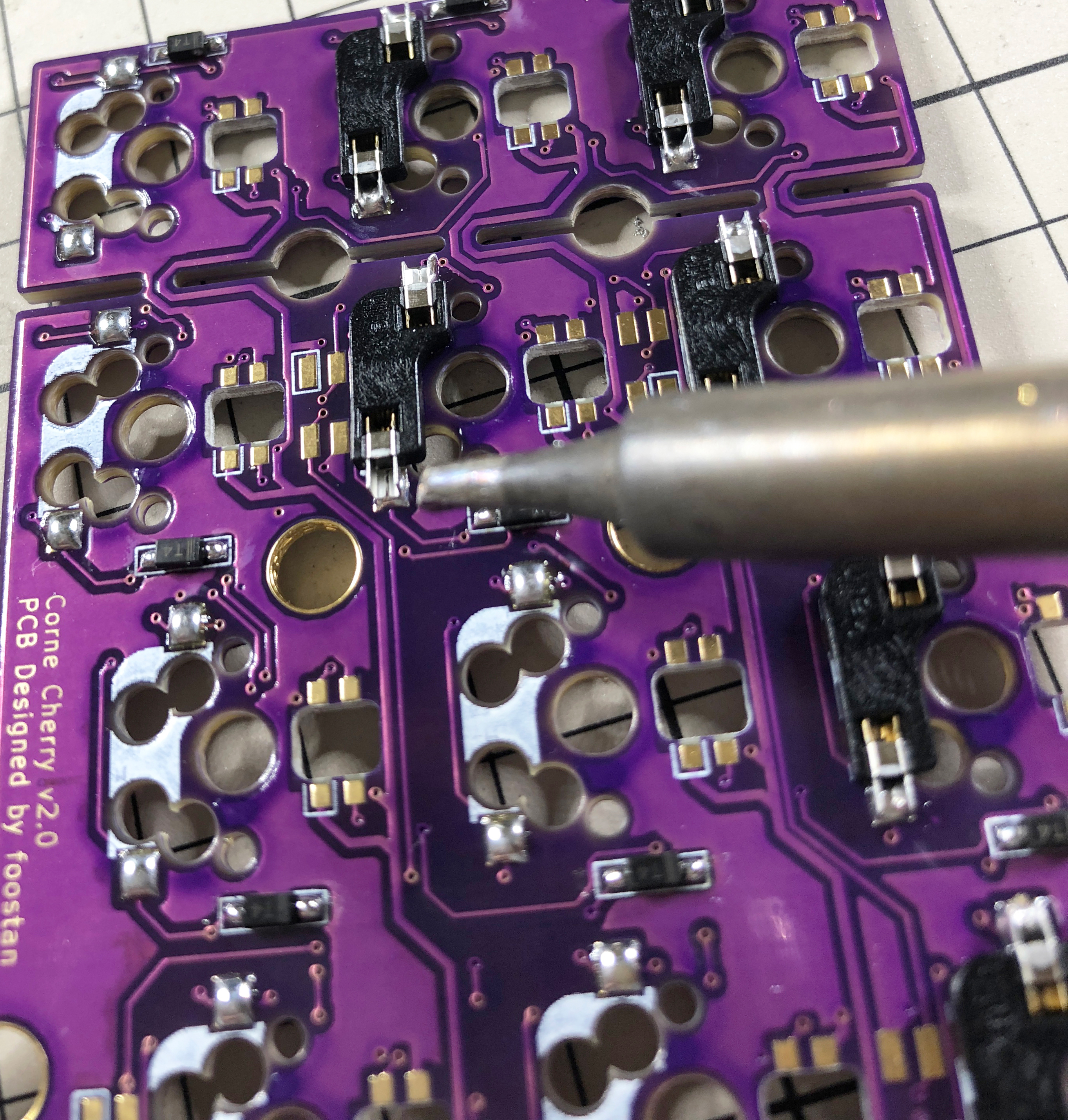
Next, solder one leg of the diode so that the spare solder melts. At this time, it is recommended to use reverse-action tweezers, because you can hold the chip parts firmly without exerting force and you can concentrate on alignment and soldering. Also, if the soldering iron is too hot or the solder is touched too much, the flux contained in the solder may evaporate and form a clean pile of solder, but it can be repaired later, so at this point you should only care about attaching parts. It's okay.
It is okay if the diode does not float when viewed from the side when one foot is attached. If it floats, press the diode with tweezers or your fingers and reheat the soldered part with a soldering iron to clean it.
Then solder the other one. Be careful not to apply too much, as a small amount of solder is sufficient. If you apply too much, you can remove it with a blotting wire or by scooping it with a soldering iron.
If the amount of solder on the preliminary solder side is small, additional soldering is performed, and if it is a mountain, apply flux from above and heat it to clean it.
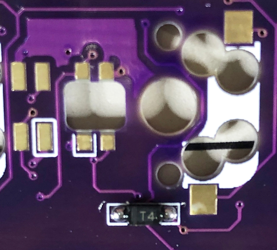
TRRS jack, reset switch
Solder the TRRS jack and reset switch to the surface of the PCB as shown in the picture below. In this build guide, the diode is attached to the back side, so it is the opposite side.
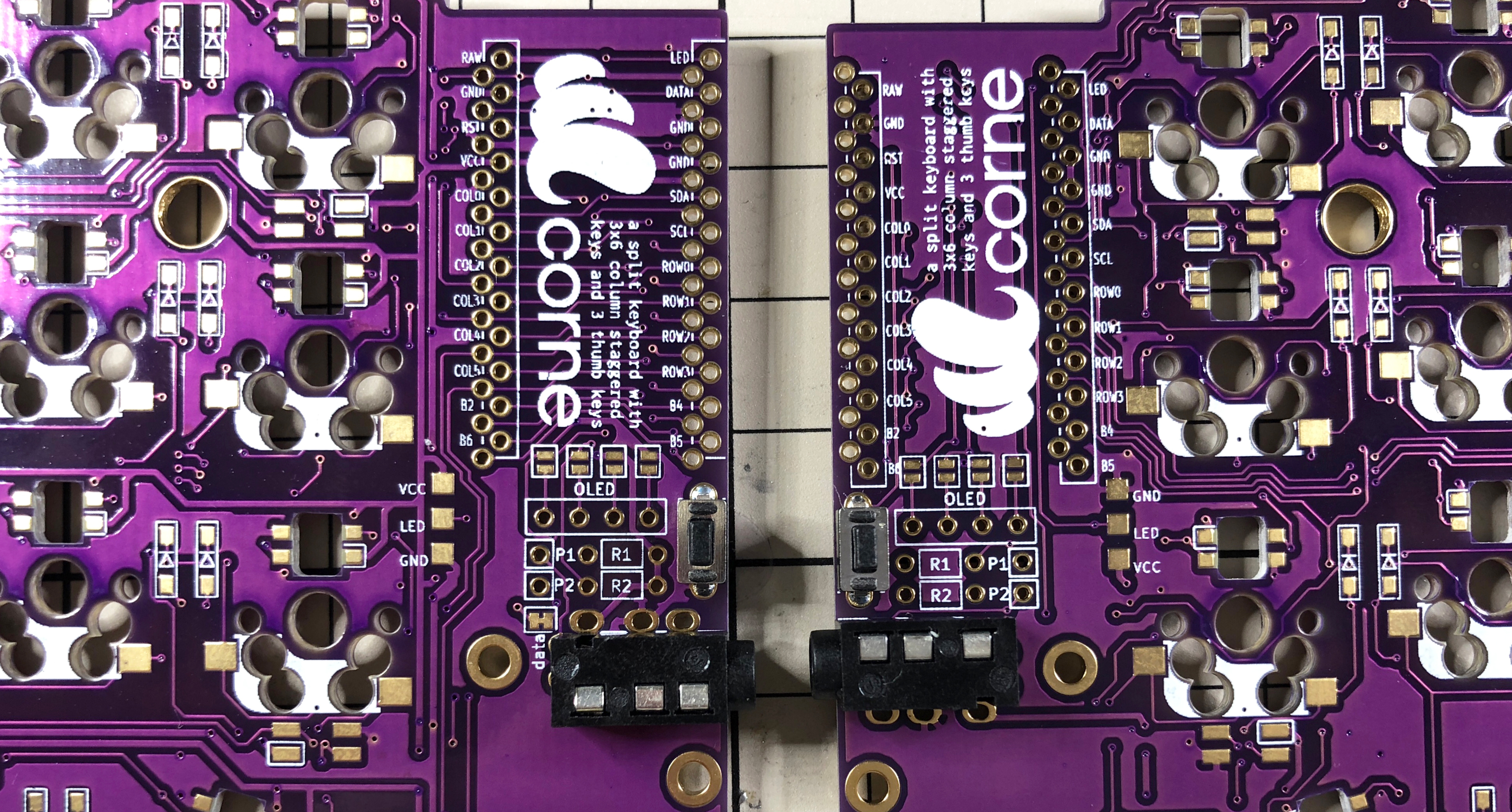
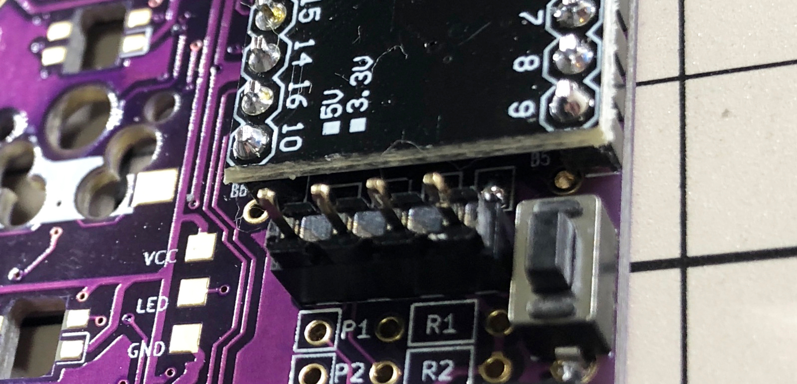
Jumpers and pin sockets for OLED modules
When using the OLED module, jumper as shown below. Please note that only the surface should be jumpered.
Solder the pin socket to the same surface.
If the jumper doesn't work, the amount of solder is probably too low or the flux in the solder has vaporized. In that case, you can fix a jumper by using a large amount of solder or applying a separate flux.
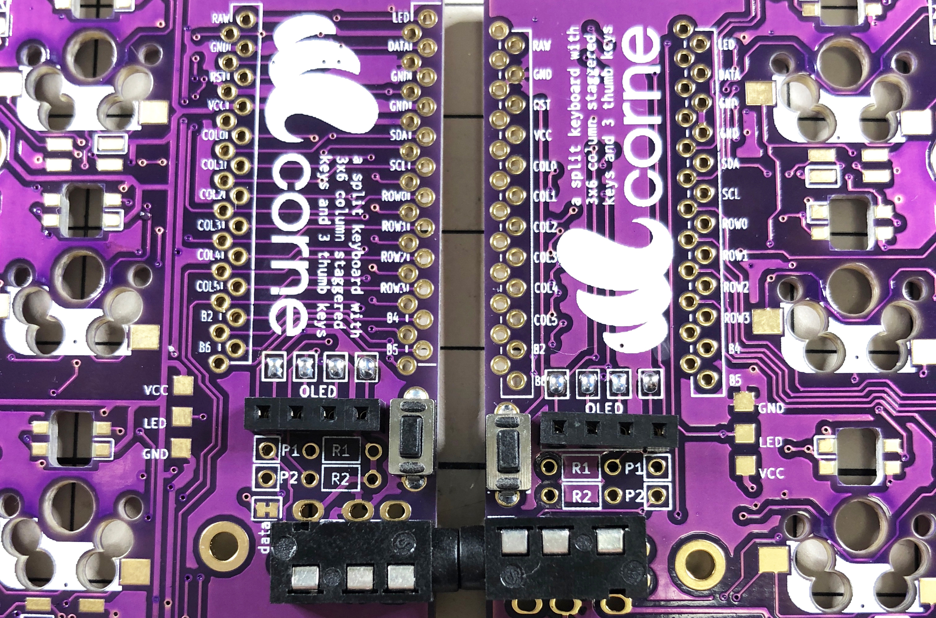
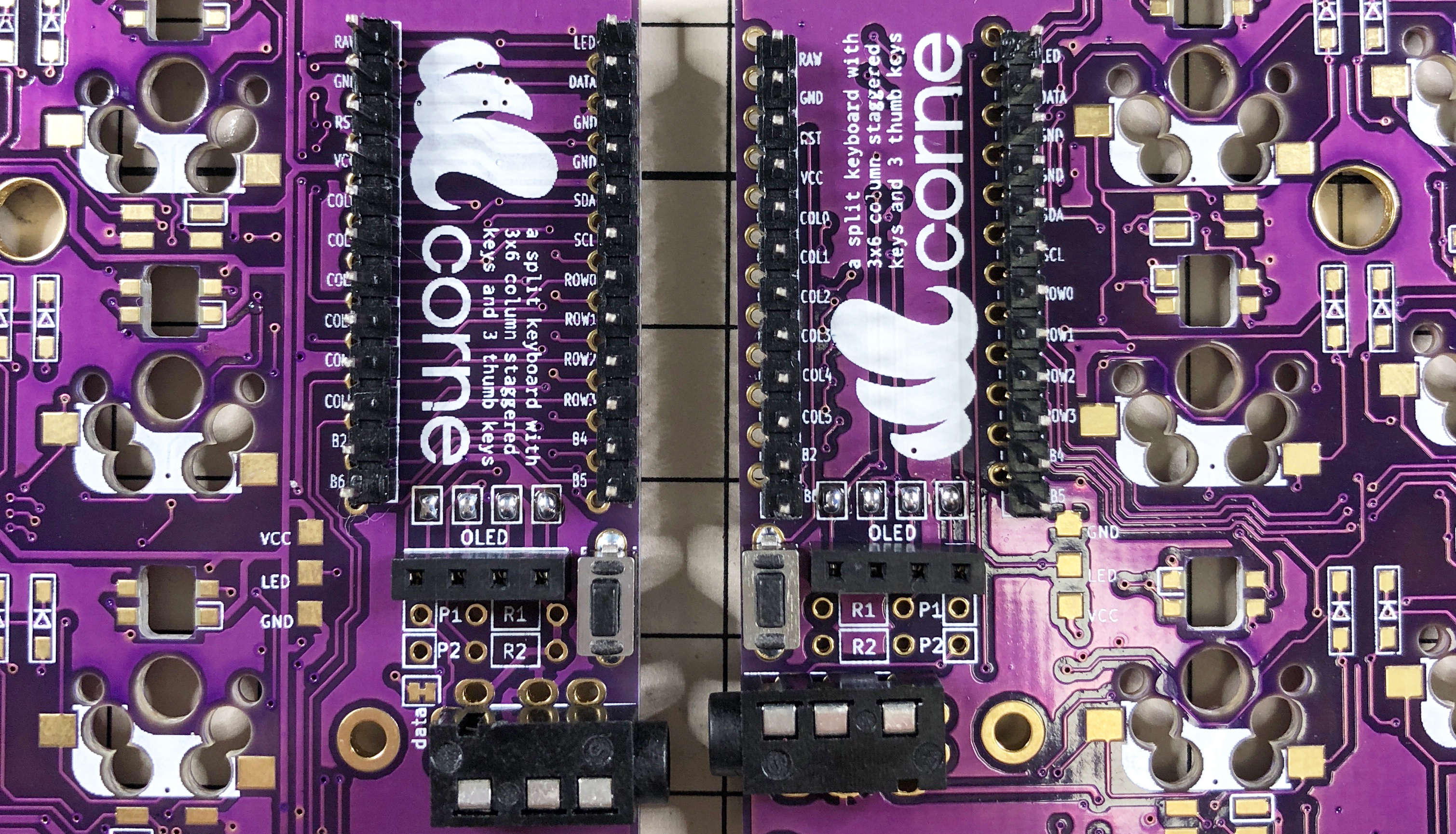
ProMicro
Solder the pin header so that it fits into the white frame, and then solder it with the back side of the Pro Micro facing up.
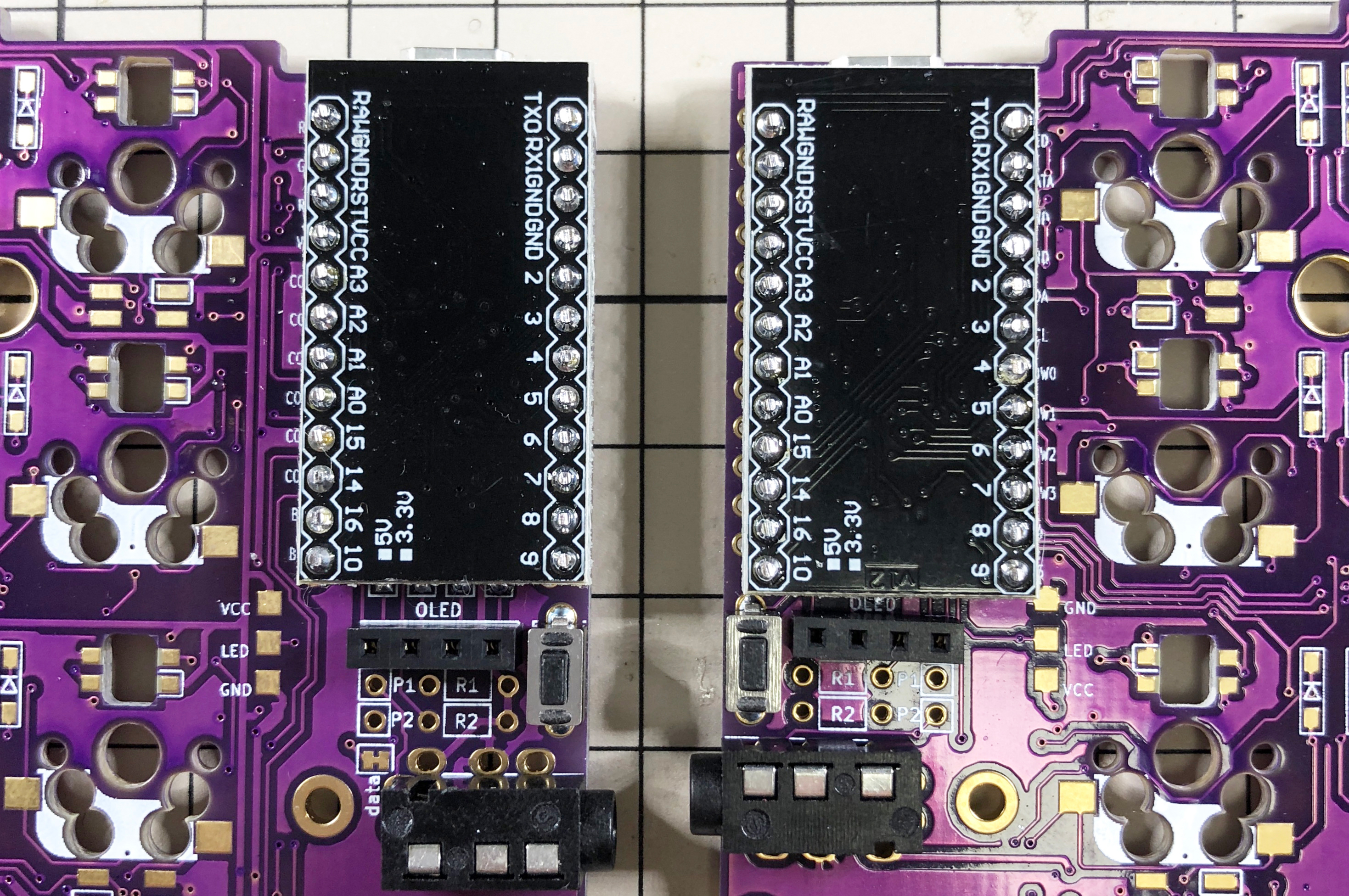
If you want to use spring-loaded pin headers, please refer to the Helix Build Guide.
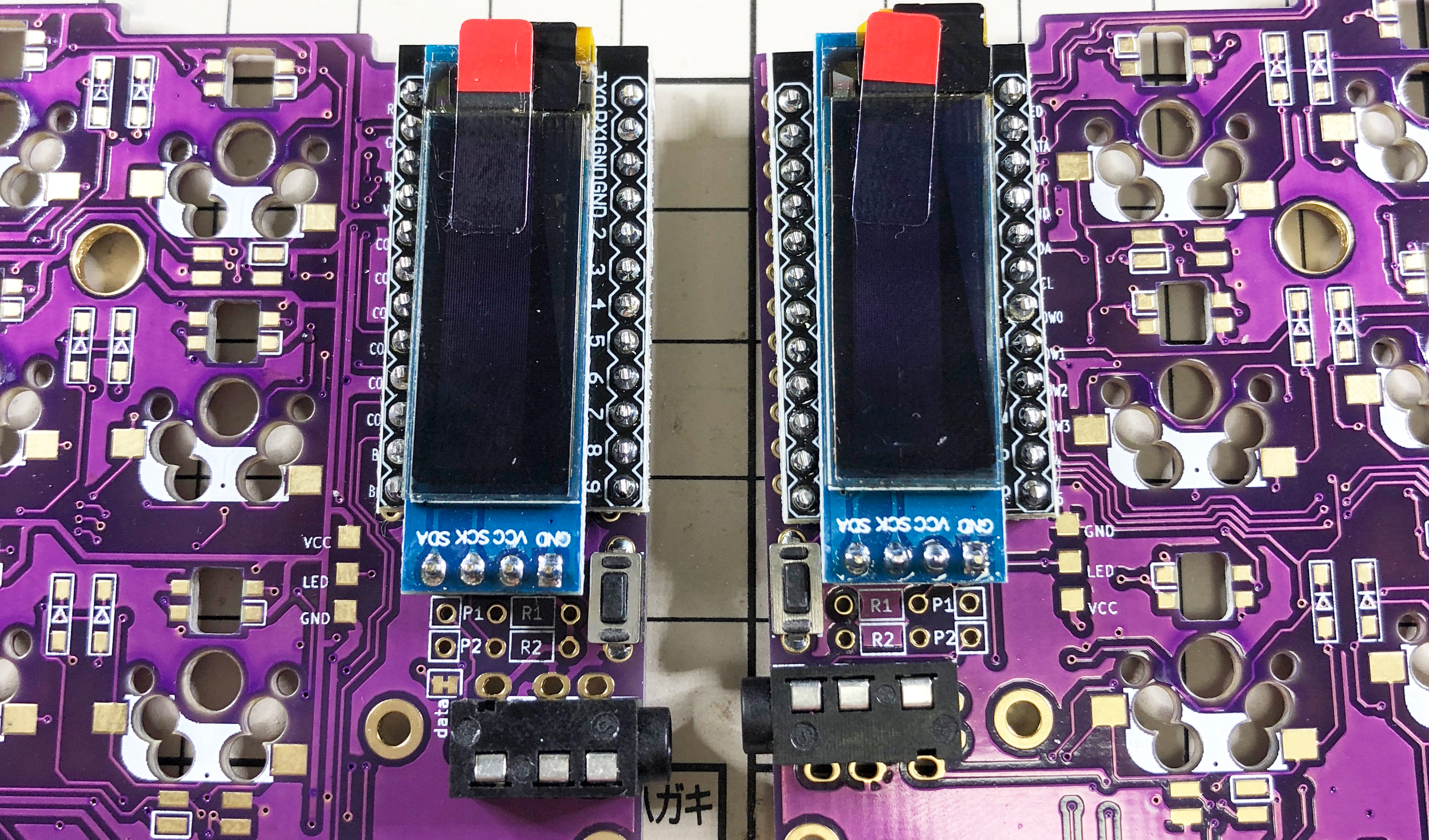
OLED module
Insert the pin header into the pin socket for OLED first, and then solder the pin header and OLED module. At this time, the OLED module is easy to float, so be careful not to float it while pressing it with your finger.
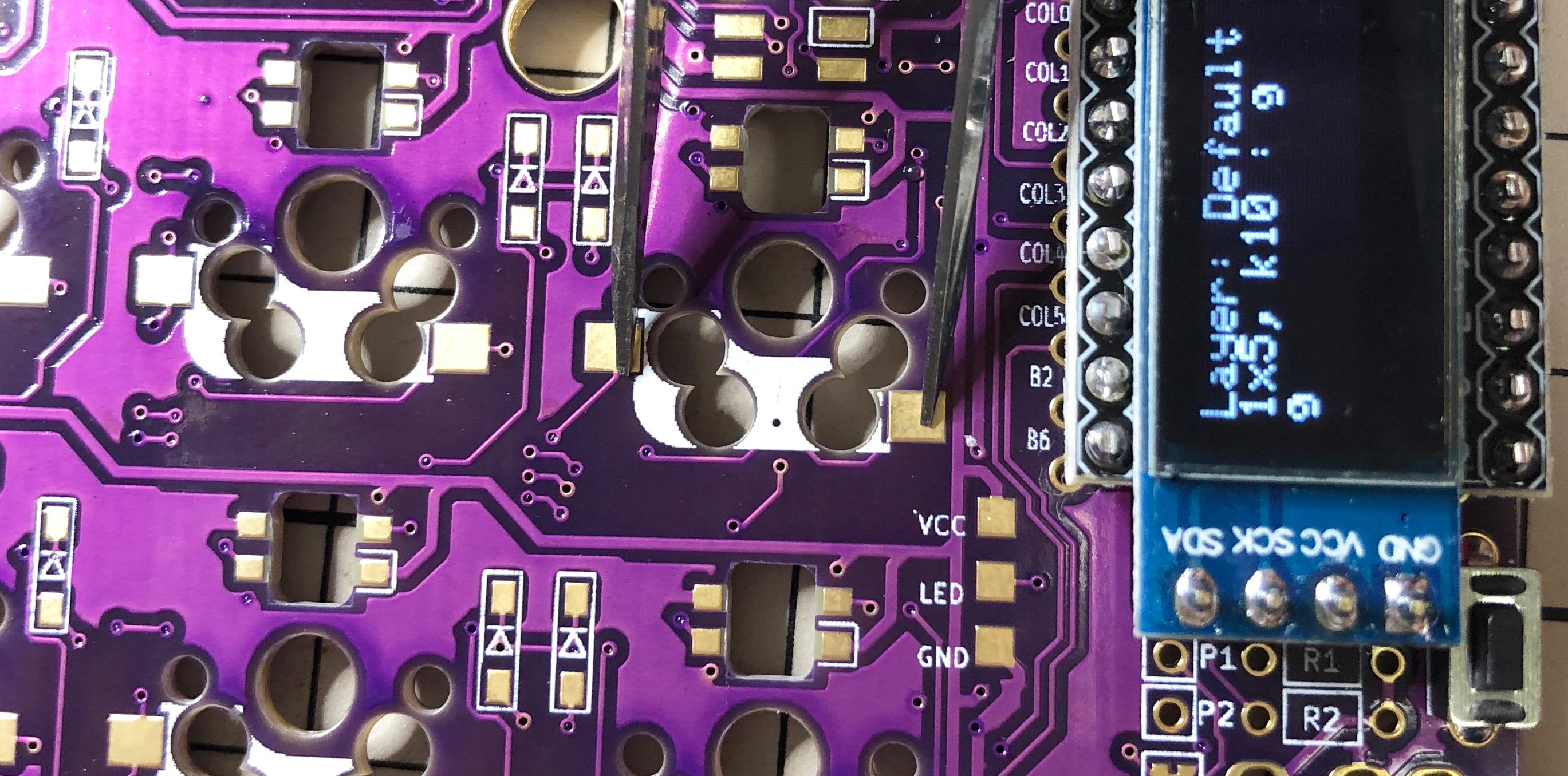
Operation check
It is recommended to check the operation when ProMicro and OLED module are attached (it will be difficult to isolate the problem if you do it at the very end).
To check the operation, first insert the firmware for crkbd into ProMicro by referring to the "Firmware" chapter below (be sure to insert it on both sides).
To check the operation, connect the left hand side to the PC with MicroUSB, and connect the left hand side and the right hand side with the TRS cable. Since there may be defects such as jacks, be sure to connect the left and right instead of one by one before checking the operation. If it is done correctly so far, if you short the pad to attach the PCB socket with tweezers etc., the key pressed on the OLED module will be displayed.
Kailh PCB Socket
Fill the pads on both sides of the back with solder. It is difficult to add it later, so please add more in advance.
Insert the socket and attach it by melting the solder you have. At this time, hold it down with tweezers or your fingers so that the socket does not float.
Soldering is now complete. If you want to add an LED as an option, refer to the "LED" chapter below (it can be attached even after installing the socket).
Plates, switches
First, insert the switch into the top plate. It's okay to do it later, but it's easier to put it in first, because it's necessary to insert the switch from a little bit.
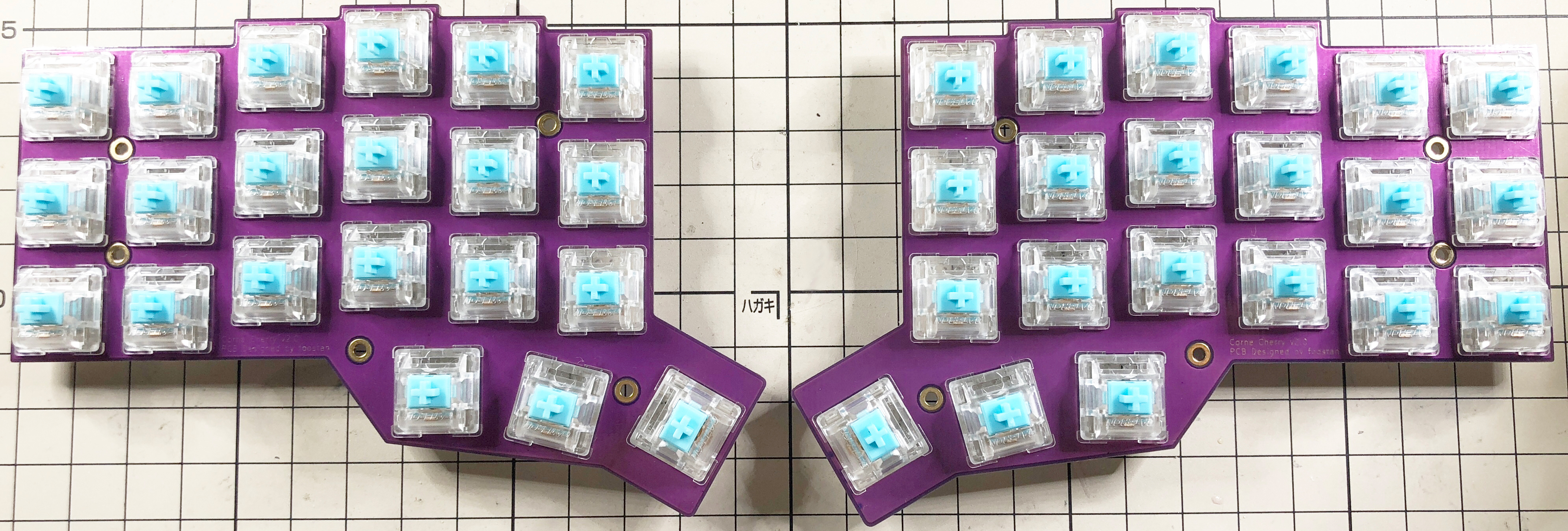
Finally, attach the spacers with screws so that the top plate, PCB, and bottom plate are in that order, and attach the cushion rubber to the four corners to complete the process.
Firmware
Write the firmware to ProMicro by referring to the following.
https://github.com/foostan/crkbd/blob/master/doc/firmware_en.md
LED (optional)
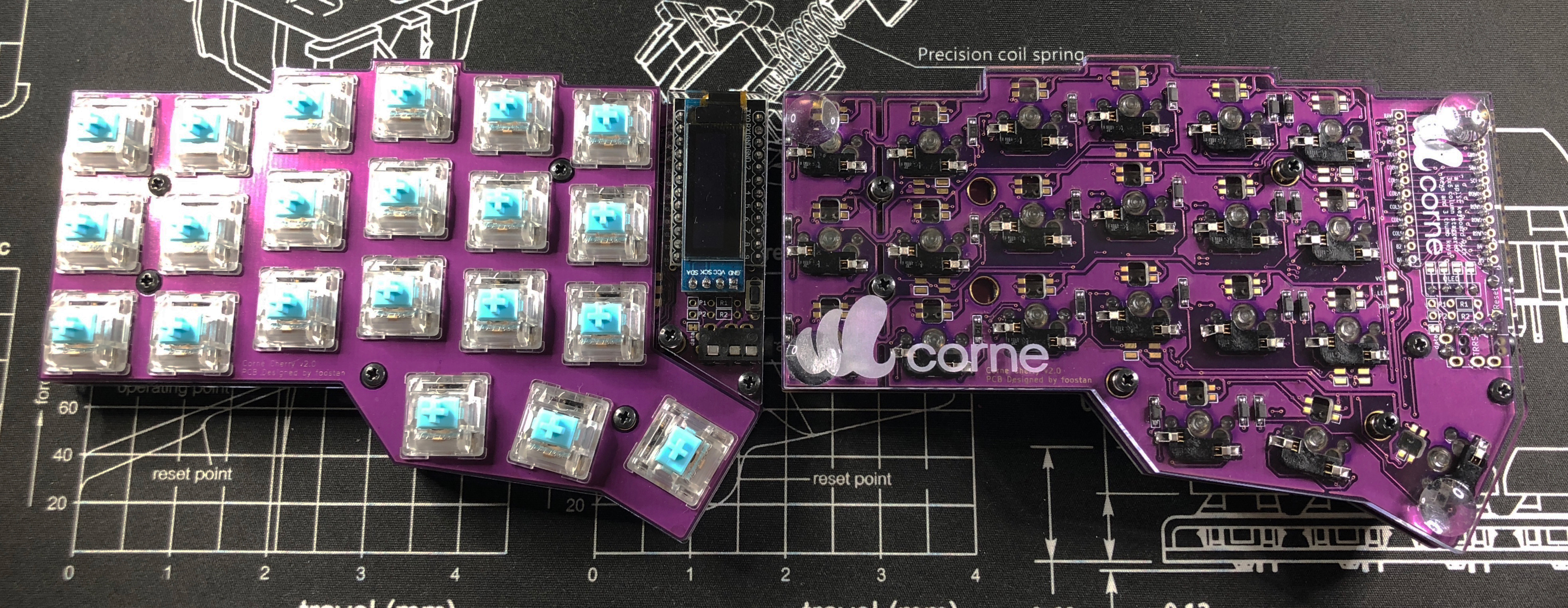
I will install the SK6812 MINI.
The SK6812MINI is extremely heat sensitive and breaks easily. We recommend using a soldering iron with a temperature control function and working at a temperature of 220°C to 270°C. Even if the temperature is adjusted, it will be damaged if the iron is applied to the LED for a long time, so try to solder as quickly as possible. The LEDs are soldered four by four, but it is recommended that you do not do four at a time, but two at a time to prevent the LED temperature from rising, as it will be less likely to break.
First, check the mounting position.
Solder 1 to 6 so that the back side (Undergrow) shines, and 7 to 27 so that the front side (Backlight) shines. Below is the position to install the LED.
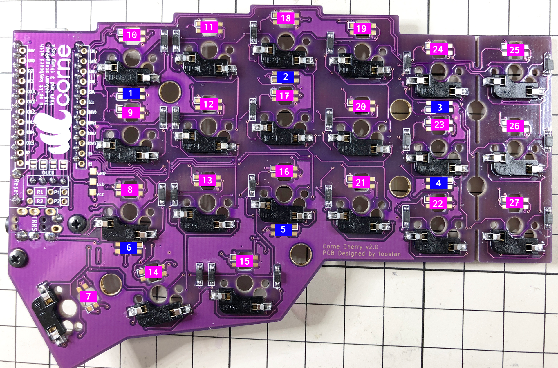
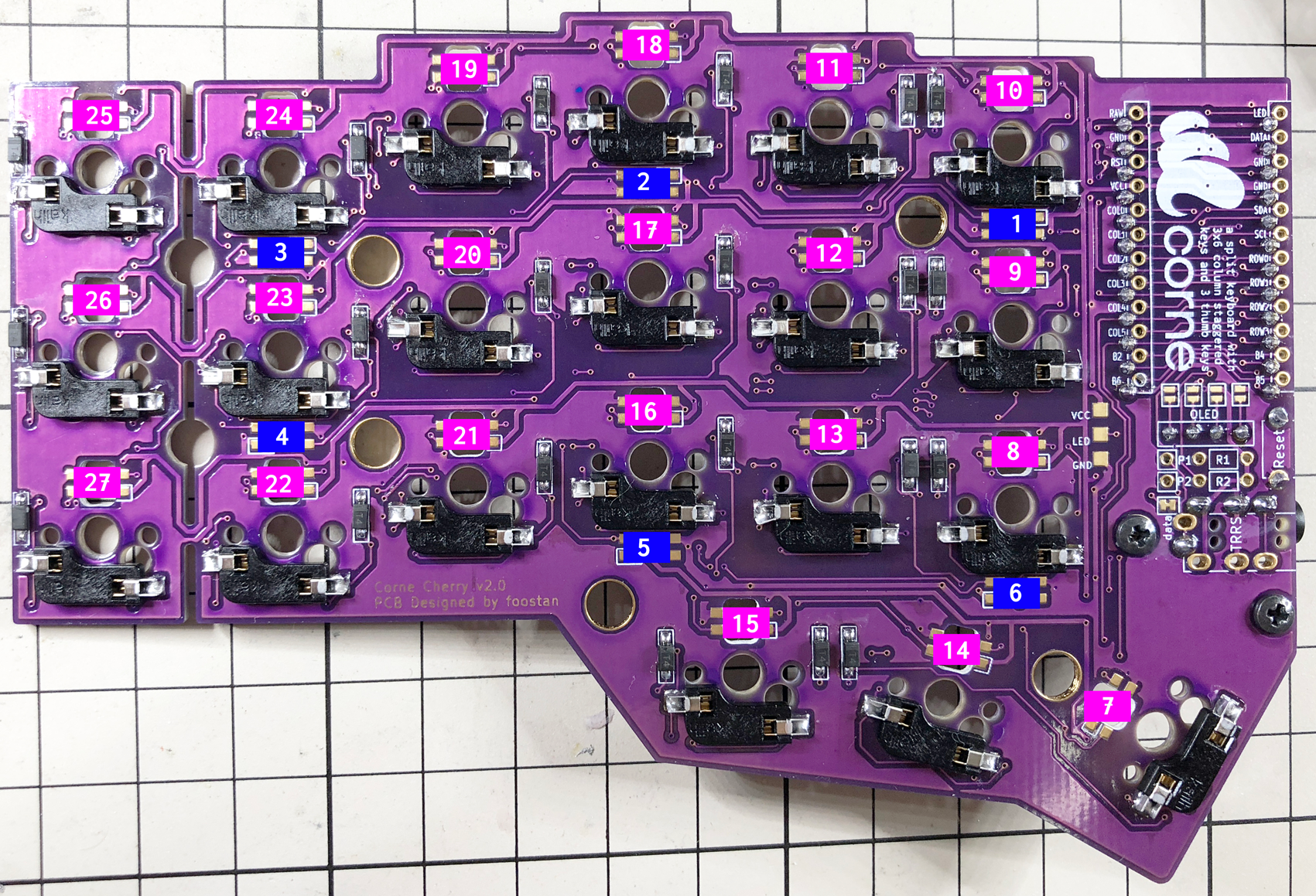
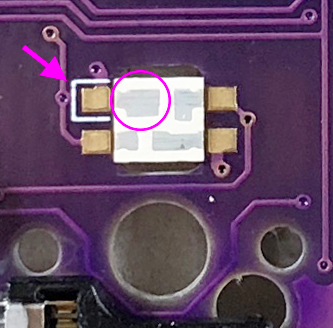
Solder 1 to 6 so that the black part circled as shown below is on the bottom and the silk mark indicated by the arrow is on the top. Please note that the orientation changes between 1 ~ 3 and 4 ~ 5.
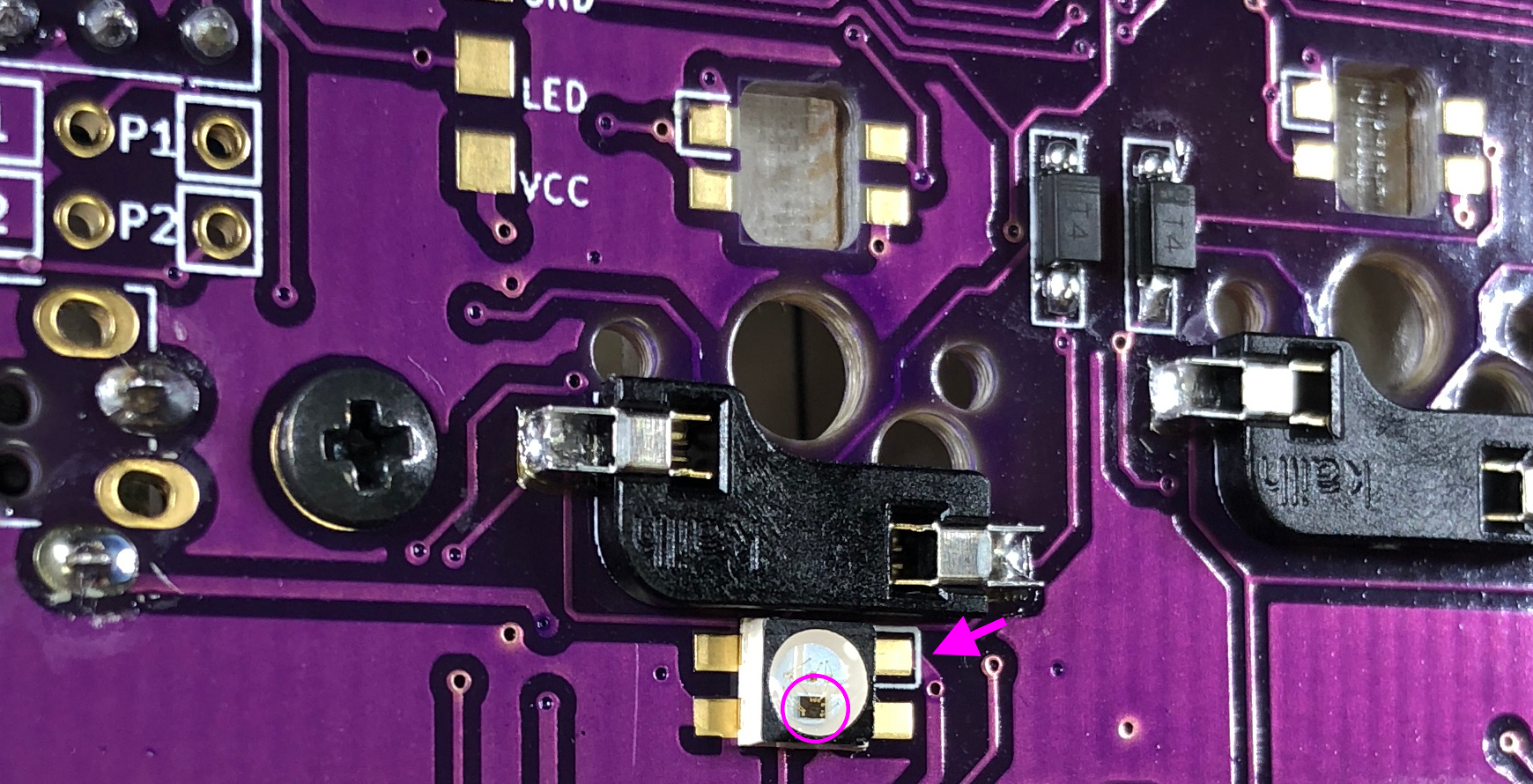
Solder 7 to 27 so that the largest pad circled and the silk mark indicated by the arrow are adjacent to each other, as shown below.
If everything can be soldered normally, it will shine as shown below. If it shines only halfway, the LEDs are connected in numerical order, so suspect that the LED that does not shine or the LED in front of it is soldered incorrectly or that the LED is damaged.
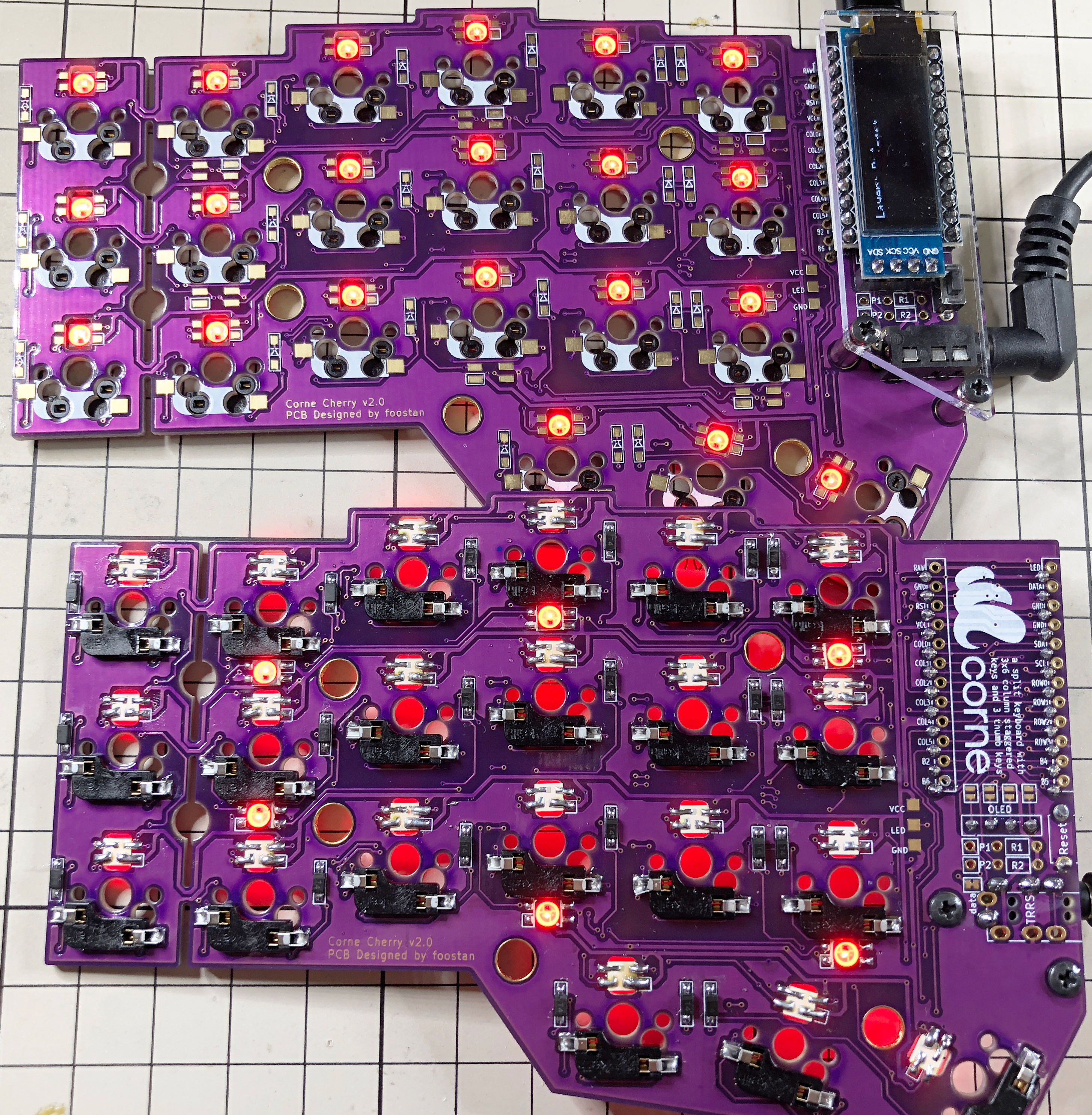
That's all there is to it.