mirror of https://github.com/foostan/crkbd.git
255 lines
9.0 KiB
Markdown
255 lines
9.0 KiB
Markdown
# Build Guide
|
|
|
|
This is the build guide for Corne Cherry v3.
|
|
[Click here for the Corne Cherry v2 build guide](
|
|
https://github.com/foostan/crkbd/blob/master/corne-cherry/doc/v2/buildguide_en.md).
|
|
|
|
## Parts
|
|
|
|
### Required
|
|
|
|
| Name | Count | Remarks |
|
|
|:-|:-|:-|
|
|
| PCB | 1 set | |
|
|
| Top plate | 2 sheets | 1.5mm-3mm thick |
|
|
| Bottom plate | 2 sheets | |
|
|
| OLED cover | 2 sheets | |
|
|
| ProMicro | 2 | Alternative: [Elite-C](https://deskthority.net/wiki/Elite-C) |
|
|
| TRRS jack | 2 | |
|
|
| Reset switch | 2 | |
|
|
| Diodes | 42 | SMD Only (SOD-123 Package) |
|
|
| PCB sockets | 42 | Compatible with Kailh and Gateron |
|
|
| Key switches | 42 | Only compatible with MX style |
|
|
| Keycaps | 42 pieces | 1u 40 pcs, 1.5u 2 pcs |
|
|
| Spacer M2 7.5mm | 10 pieces | For Case assembly |
|
|
| Spacer M2 9mm | 4 pieces | For OLED cover |
|
|
| Screw M2 4mm | 28 screws | |
|
|
| Rubber feet | 8 pieces | |
|
|
| TRRS (4 poles) cable | 1 | TRS (3 poles) cable is also compatible |
|
|
| Micro USB cable | 1 | Avoid charge-only cables |
|
|
|
|
### Optional
|
|
|
|
| Name | Count | Remarks |
|
|
|:-|:-|:-|
|
|
| OLED module | 2 | |
|
|
| SK6812MINI-E | 42 | LEDs for Backlight |
|
|
| WS2812B | 12 | LEDs for Undergrow |
|
|
| [Microcontroller/OLED Sockets](https://www.digikey.com/en/products/detail/315-43-112-41-003000/ED4764-12-ND/4455232) | 1 | Alternative: [2.54 1row femal sliv](https://www.aliexpress.com/item/4001122376295.html) option |
|
|
| [Microcontroller Pins](https://www.digikey.com/en/products/detail/mill-max-manufacturing-corp/3320-0-00-15-00-00-03-0/4147392) | 48 | Alternative: Diode/Resistor legs |
|
|
| [OLED Headers](https://www.digikey.com/en/products/detail/mill-max-manufacturing-corp/350-10-164-00-006000/357045) | 1 | Soldered to OLED module |
|
|
|
|
## Firmware preparation
|
|
|
|
If you build the firmware yourself, it will take some time to set up the environment,
|
|
so it's best to start at the beginning.\
|
|
It is recommended to flash ProMicro's prior to soldering.\
|
|
For more information,
|
|
please see <https://github.com/foostan/crkbd/blob/master/docs/firmware/firmware_en.md>.
|
|
|
|
## Verification
|
|
|
|
The PCB for Corne Cherry v3 is as follows.
|
|
Make sure it is the same as your PCB.
|
|
|
|

|
|
|
|

|
|
|
|
The PCB comes with a frame for manufacturing reasons.
|
|
You can fold it by hand to remove it, but if it is difficult,
|
|
make a cut in the joint\* with a cutter or similar,
|
|
to make it easier to remove.
|
|
In addition, the joint can be cleaned with a file.
|
|
|
|
\**Joint part: There are a total of 8 parts,
|
|
which are marked in red in the image below.*
|
|
|
|

|
|
|
|
## Assembly
|
|
|
|
### Diodes
|
|
|
|
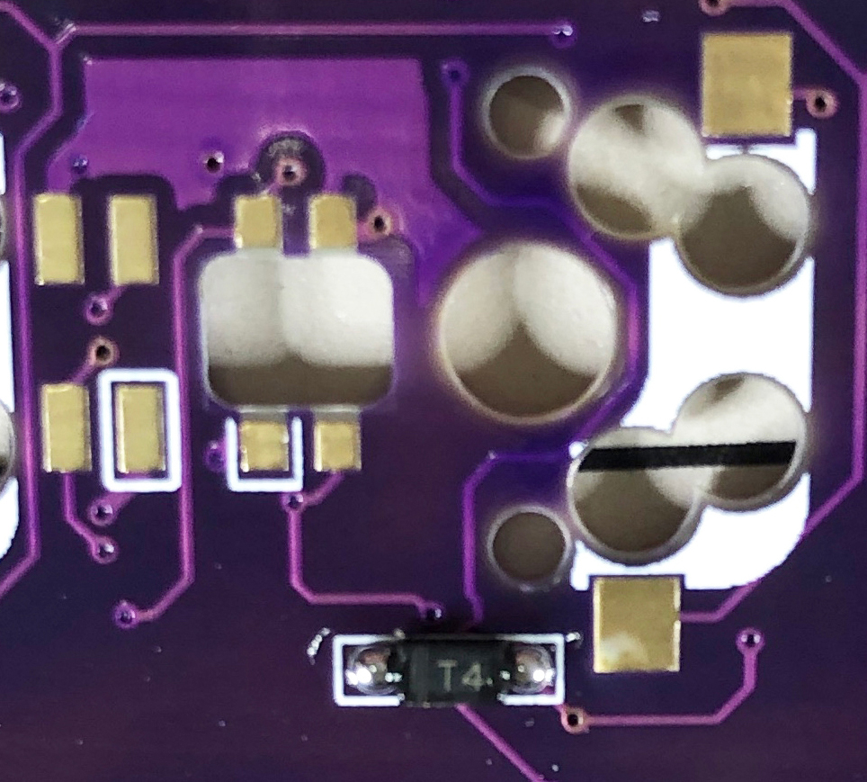
Since SMD parts are very small, fine-tip/reverse-action tweezers are recommended.
|
|
|
|
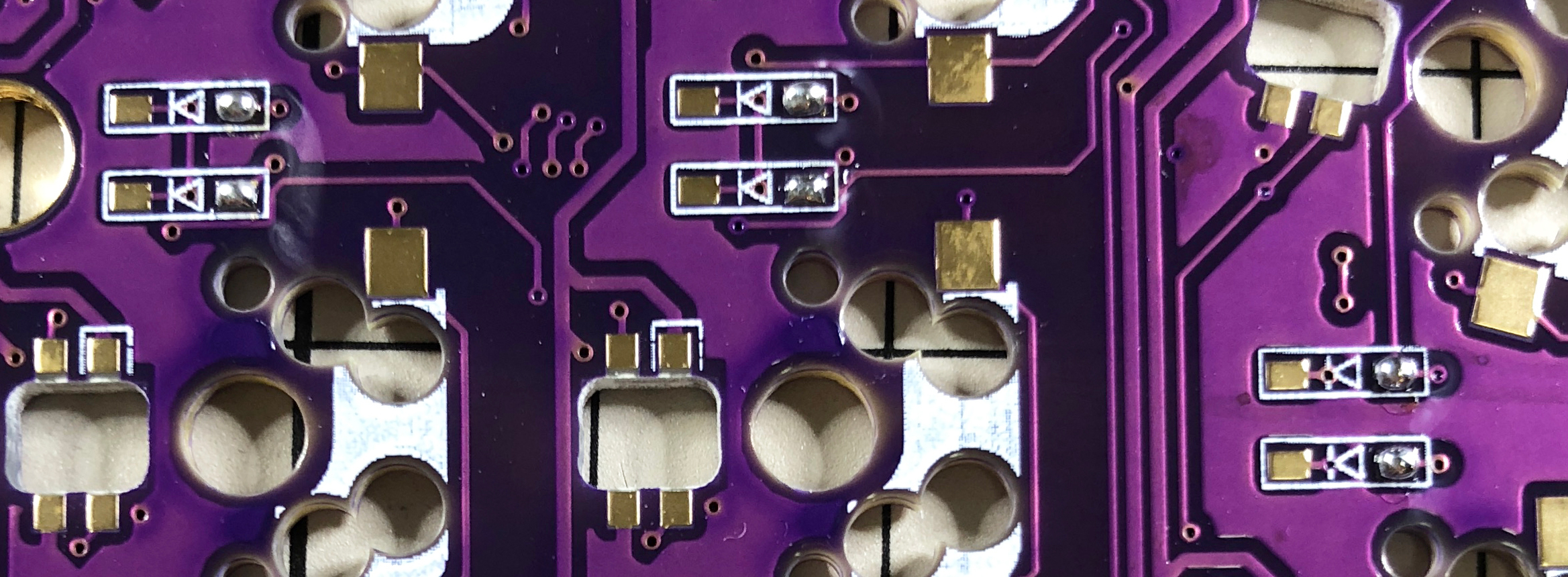
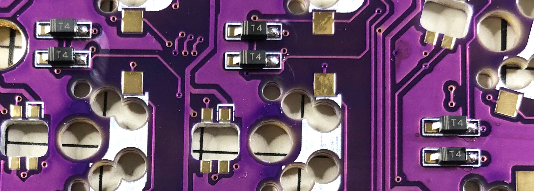
**The diodes have a specific orientation**, so install with "|" marking on the diode
|
|
facing the "|" on the PCB marking: "|◁"
|
|
|
|

|
|
|
|
<details>
|
|
<summary>TIPS: Tips for installing SMD parts</summary>
|
|
|
|
Begin with applying solder to only one pad.
|
|
|
|
|
|
|
|
Next, place SMD component while heating solder. At this time,
|
|
it is recommended to use [reverse-action tweezers](https://www.alimed.com/_resources/cache/images/product/70895A_850x480-pad.jpg),
|
|
so that you can hold the SMD part firmly without applying force,
|
|
and concentrate on alignment and soldering instead.
|
|
Also, if the soldering iron is too hot or the solder is touched too long,
|
|
the flux contained in the solder may evaporate and form a poor solder joint,
|
|
but it can be repaired later,
|
|
so at this point you should only care about attaching parts.
|
|
It's okay.
|
|
|
|
|
|
|
|
It is okay if the SMD component is not flush with the PCB when viewed from the side.
|
|
If it is floating, press the SMD component down with tweezers or your finger and reheat the solder.
|
|
|
|
|
|
|
|
Then solder the other contacts.
|
|
Be careful not to apply too much solder,
|
|
as a small amount is sufficient.
|
|
If you have applied too much,
|
|
you can remove it with a suction pump, solder wick,
|
|
or by picking it up with a soldering iron.
|
|
|
|
If the amount of solder on the preliminary solder side is small,
|
|
additional soldering is performed, and if it is a heap,
|
|
apply flux from above and heat it to clean it.
|
|
|
|
|
|
|
|
</details>
|
|
|
|
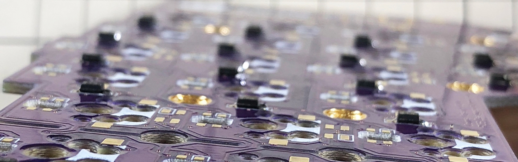
The diode is completed by soldering 42 pieces in total on the left and right.
|
|
|
|

|
|
|
|
### LED (optional)
|
|
|
|
Solder the SK6812MINI-E and WS2812B.
|
|
|
|

|
|
|
|
All soldering is done from the back side, but the SK6812MINI-E is for Backlight
|
|
(the front side is shining) and the WS2812B is for Undergrow (the back side is shining).
|
|
|
|

|
|
|
|
#### WS2812B (Undergrow)
|
|
|
|
First, solder the WS2812B.
|
|
|
|
Match recessed corner of the LED with marked corner on the PCB as shown below.
|
|
Refer to **TIPS: Tips for installing SMD parts** section above as similar soldering
|
|
procedure is followed.
|
|
|
|

|
|
|
|
WS2812B LED soldering is completed after 12 are installed on left and right.
|
|
|
|

|
|
|
|
#### SK6812MINI-E (Backlight)
|
|
|
|
Then solder the SK6812MINI-E.
|
|
|
|
Match the notched corner of the LED with the marked corner on the PCB as show below.
|
|
Refer to **TIPS: Tips for installing SMD parts** section above as similar soldering
|
|
procedure is followed.
|
|
These are more resilient than the SK6812MINI LEDs,
|
|
but still may be damaged if directly exposed to the heat of a soldering iron.
|
|
~320°C seems to be an ok temperature, evne if all four legs are soldered
|
|
one after another.
|
|
|
|

|
|
|
|
SK6812MINI-E LED soldering is completed after 42 are installed on left and right.
|
|
|
|

|
|
|
|
### TRRS jack, reset switch, pin socket for OLED
|
|
|
|
Solder the TRRS jack, reset switch (tact switch),
|
|
and OLED pin socket as shown in the picture below.
|
|
|
|

|
|
|
|
Since these parts may fall off when soldering, you can affix them with masking tape.
|
|
|
|
### ProMicro
|
|
|
|
Solder headers to PCB. Then solder ProMicro to headers, with components facing PCB as shown below.
|
|
|
|

|
|
|
|
If you use [spring-loaded pin headers](https://shop.yushakobo.jp/collections/all-keyboard-parts/products/31),
|
|
you do not need to solder the back side.
|
|
Please refer to the [Helix Build Guide](
|
|
https://github.com/MakotoKurauchi/helix/blob/master/Doc/buildguide_en.md#pro-micro)
|
|
for details on how to use spring-loaded pin headers.
|
|
|
|

|
|
|
|
### OLED module
|
|
|
|
Insert the pin header into the socket first, then solder the OLED module
|
|
to the pin header.
|
|
Note: Solder one pin to OLED module, then reheat solder to confirm OLED module is level,
|
|
then solder remaining pins.
|
|
|
|

|
|
|
|
### Operation check
|
|
|
|
Now is a good time to test your keyboard to help isolate potential problems.
|
|
|
|
To check the operation, connect left and right sides with TRRS cable,
|
|
then connect left side to the computer with USB cable.
|
|
If it is done correctly so far, shorting a hotswap socket pad with tweezers will
|
|
output out a keypress and it will be displayed on the OLED module.
|
|
|
|
### Switch Sockets
|
|
|
|
Solder hotswap sockets according to mark on PCB as shown below.
|
|
Refer to **TIPS: Tips for installing SMD parts** section above as similar soldering
|
|
procedure is followed.
|
|
|
|

|
|
|
|
Switch Socket soldering is completed after 42 are installed on left and right.
|
|
|
|

|
|
|
|
### OLED protective cover
|
|
|
|
Attach the OLED protective cover with M2 9mm spacers and M2 screws.
|
|
|
|

|
|

|
|
|
|
### Plates & Switches
|
|
|
|
Place a few key switches into the top plate, then line up and press into PCB socket.
|
|
If you attach all the key switches to the top plate first,
|
|
it will be more difficult to fit them in the PCB sockets all at once.
|
|
So it is recommended to do a few to begin with.
|
|
|
|

|
|
|
|
Install the M2 7.5mm spacer and M2 screws on the top plate.
|
|
|
|

|
|
|
|
It is easy to screw the spacer in after inserting it into the hole from the back side.
|
|
|
|

|
|
|
|
Attach the bottom plate with M2 screws.
|
|
|
|

|
|
|
|
Install the rubber feet in the following positions.
|
|
|
|

|
|
|
|
That's it!
|
|
|
|

|