15 KiB
Build Guide
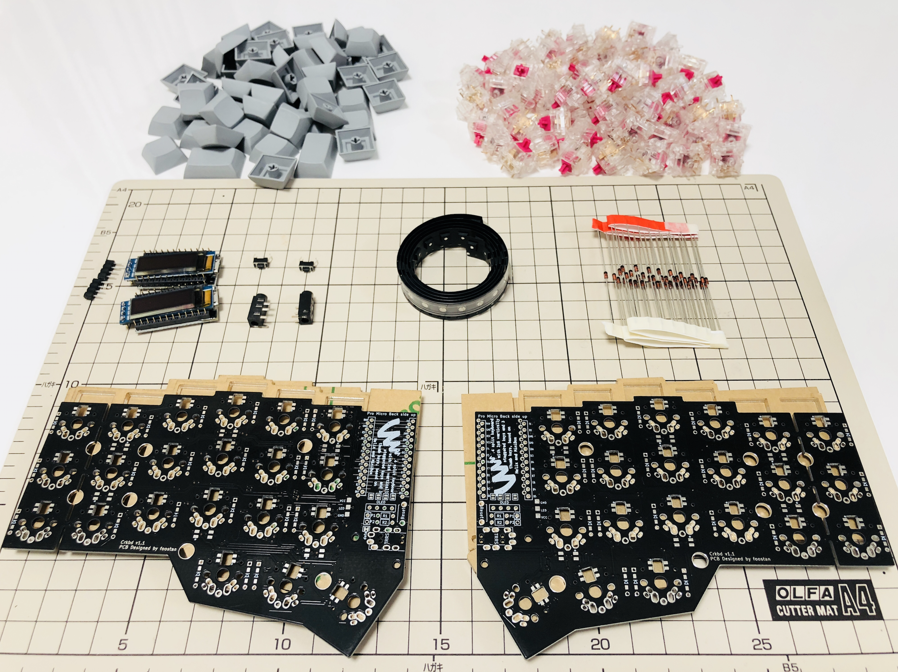
Parts
Required
| Name | Count | Remarks |
|---|---|---|
| PCB | 2 | |
| Plate | 2 sets | |
| ProMicro | 2 | |
| TRRS Jack | 2 | |
| TRS(3 pole) cable | 1 | TRRS(4 pole) cable works too. |
| Tact switch | 2 | |
| Diode | 42 | You need SMD for low profile. |
| Key Switch | 42 | |
| Key Cap | 42 | 1u x 40, 1.5u x 2 |
| Spacer M2 7.5mm | 10 | use 3mm for low profile |
| Spacer M2 9mm or 11mm | 4 | |
| Screw M2 4mm | 28 | |
| Rubber foot | 10 |
Optional
| Name | Count | Remarks |
|---|---|---|
| OLED Module | 1 or 2 | |
| 4x1 Pin Male Header | 2 | For OLED |
| 4x1 Pin Female Socket | 2 | For OLED |
| SK6812MINI | 54 | Front side x 42, back side x 12 |
| Addressable LED Strip | 2 | exclusive with SK6812MINI |
Advance preparation
If you build the firmware yourself,
it will take some time to set up the environment,
so it's best to start at the beginning.
For more information,
please see https://github.com/foostan/crkbd/blob/master/doc/firmware_en.md.
Soldering
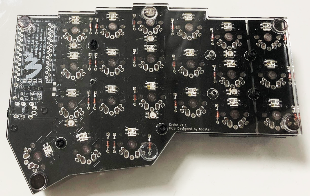
PCB is reversible; use one for the left hand side and the other for the right.
Diodes
For non Low Profile keyswitches
Solder diodes as indicated in the picture. You can place it on either side, but front side is recommended if you implement under-glow LED. You can use SMD diodes too.
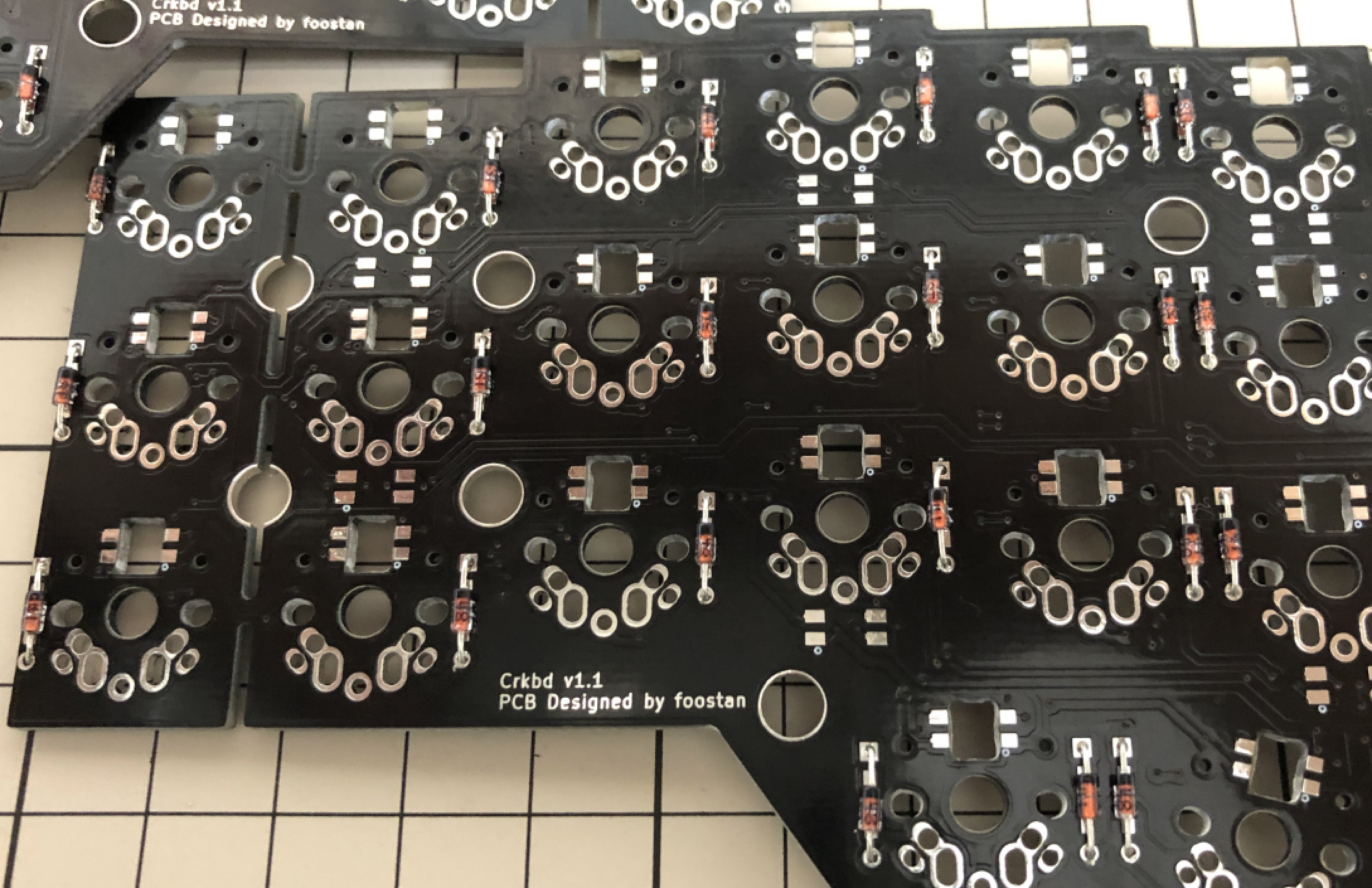
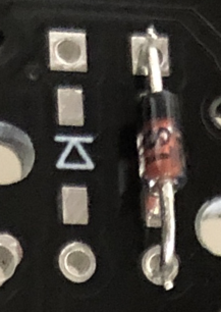
Diode has polarity; make sure to match the polarity with PCB silkscreen.
<- Before | After ->
For Low Profile Keyswitches
If you use low profile keyswitches, you have to implement SMD diodes on the back side. Otherwise, diodes will interfere with top plate.
As with normal diodes, SMD diodes have polarity. The lines on the SMD diode should be on the same side as the line on the PCB silkscreen.
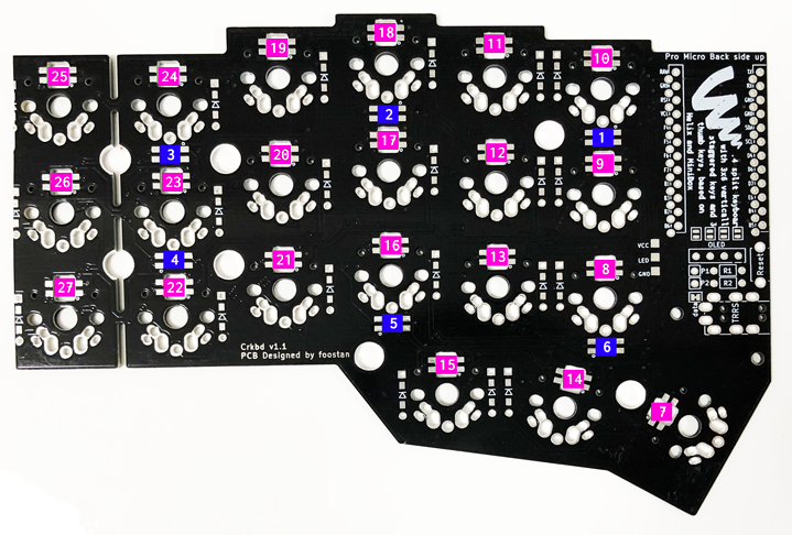
LEDs (Optional)
Implement LEDs under keyswitches (No. 7 through 27) upward facing, and others (No. 1 through 6) on the back side(under-glow), as indicated in the picture.
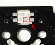
For No.7 to 27 LEDs, Install LEDs from the back side as shown below. Note the 'o' silkscreen marking and use them as a guide to implement LEDs in the direction. On some versions of the PCB (e.g. Corne-cherry v2), the 'o' silkscreen marking has been replaced by a white square around one of the pads, but the principle is still the same.
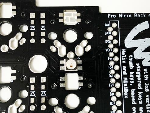
The LED has one pad that is shaped like a square. That square should connect to the pad that has the 'o' silkscreen marking:
There are many different techniques on how to solder the LEDs, but this video might give you an idea on how to do it.
For No. 1 to 6 LEDs, solder the pattern on the side of the device (highlighted in pink on the picture) and the PCB pattern (blue on the picture). Apply flux and take small amount of solder with a soldering iron and press it on the edge of the patterns.
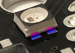
LEDs are connected in the order of the number on the picture above. If it turns on only halfway, it is likely that first LED that doesn't turn on or the last LED that turns on is not implemented correctly.
Note that the default Crkbd firmware has LEDs turned off, so you'll have to turn them on before you can test (see the firmware section for instructions how).
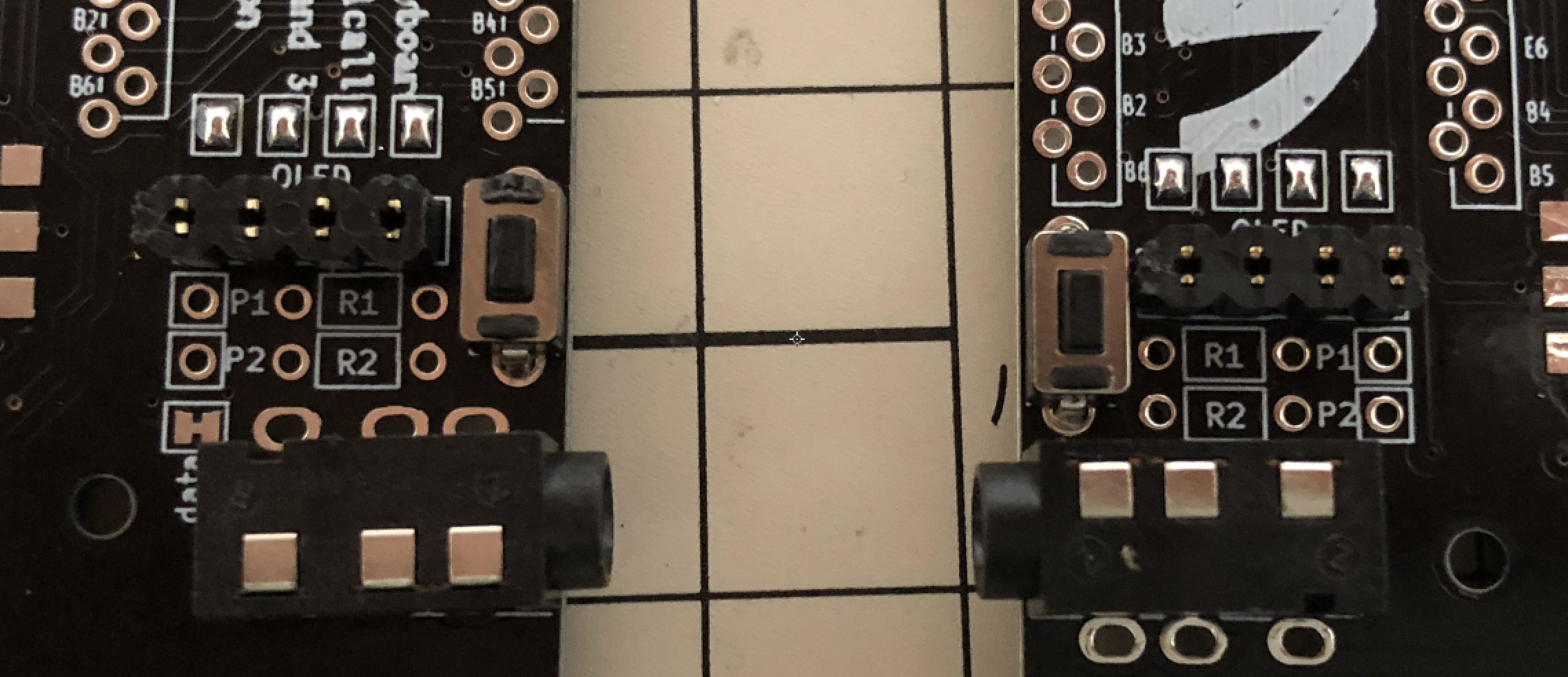
Jumpers for OLED modules (optional)
To use OLED modules, short circuit the jumper patterns. Only short circuit the front side
TRRS socket, reset switch, OLED header sockets
Install TRRS sockets and reset switches as in the picture. For OLEDs, also implement pin sockets.
ProMicro
Before you start, flash the Crkbd firmware to the ProMicros to make sure they are alright.
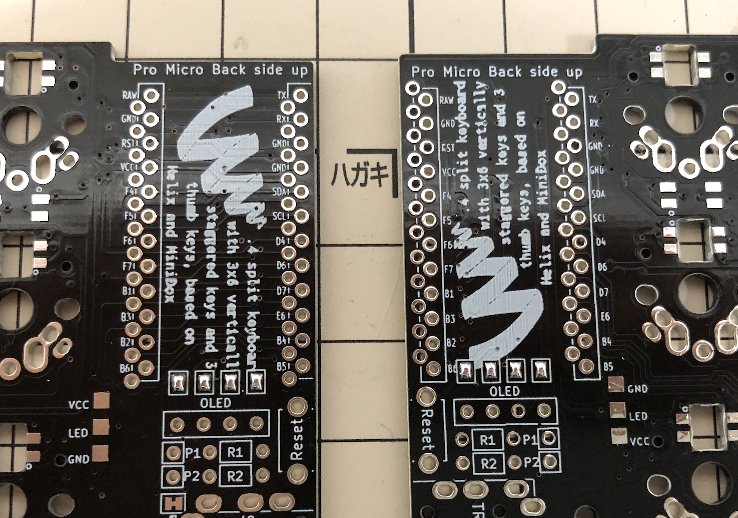
The ProMicro is then installed in the set of holes that has a white frame on the frontside of the PCB. Make sure you solder it in the right set of holes, as desoldering the ProMicro is hard. Implement pin headers in the white frame, then install ProMicro with its backside up.
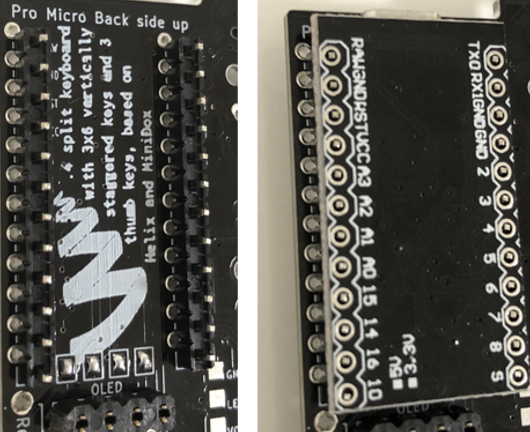
The picture is the right hand side, but it's the same for the left hand side - pins into the through holes in the white frame as seen from the frontside, placing the ProMicro with its backside up.
OLED Module
Implement pin header onto the OLED modules, then insert them into the pin sockets.
Adjust the height of the spacer accordingly to the height of pin header. Most common pin header/socket and 11mm spacers are used in the picture.
Use socket to Mount ProMicro
With using sockets for mounting ProMicro, you can replace it easily when it breaks. Two methods are introduced here.
Using Spring Loaded Header
Refer to the Helix build guide
ProMicro kit with spring loaded headers is available at Yusha-Kobo
https://yushakobo.jp/shop/promicro-spring-pinheader/
Using OLEDs available at Yusha-Kobo which come with low profile header, together with and 9mm spacers, you can build them thin and gap-less.
Using Pin Sockets
Low profile pin sockets are available from Akizuki Denshi etc. Requires some work.
http://akizukidenshi.com/catalog/g/gC-03138/
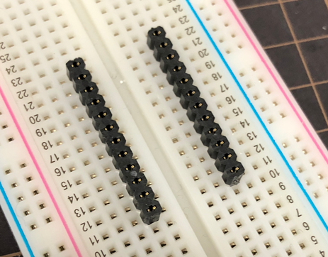
Install a couple of 12x1 pin sockets on a breadboard.
Using male 12x1 pin headers, fixate ProMicro onto the pin sockets.
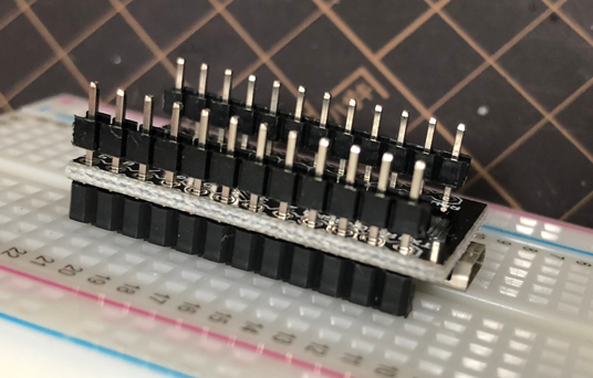
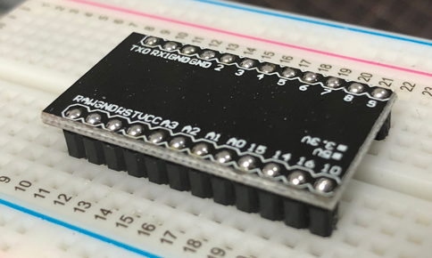
Remove plastic pin holders, solder the pins to ProMicro, and then cut extra pins.
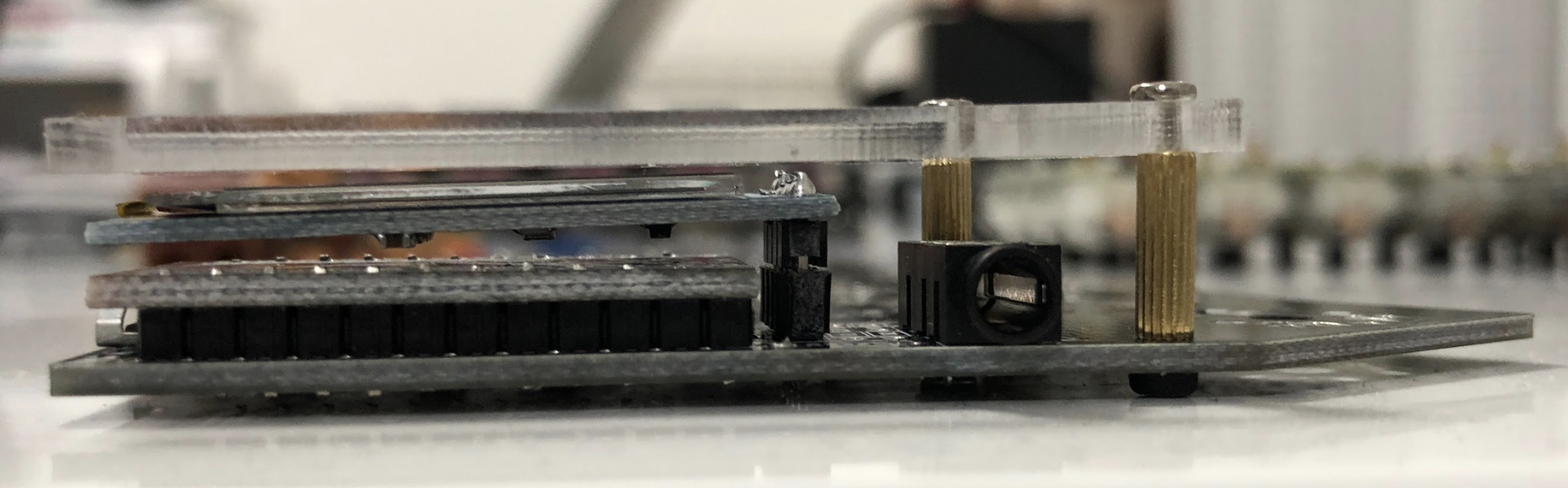
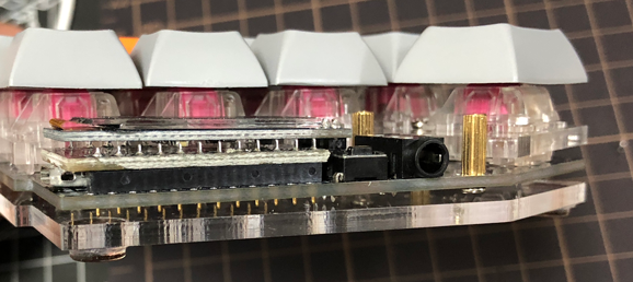
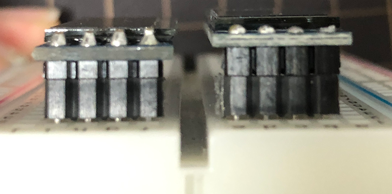
Comparison
Spring loaded headers can make the height lower.
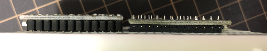
Comparing pin-headers in the picture. Headers come with OLED available at Yusha-Kobo are lower.
Testing
It is recommended to test the ProMicro and OLED modules before installing keyswitches, because rework would be difficult after that.
First, build QMK Firmware for built for Crkbd and install on ProMicro (if you haven't already done so).
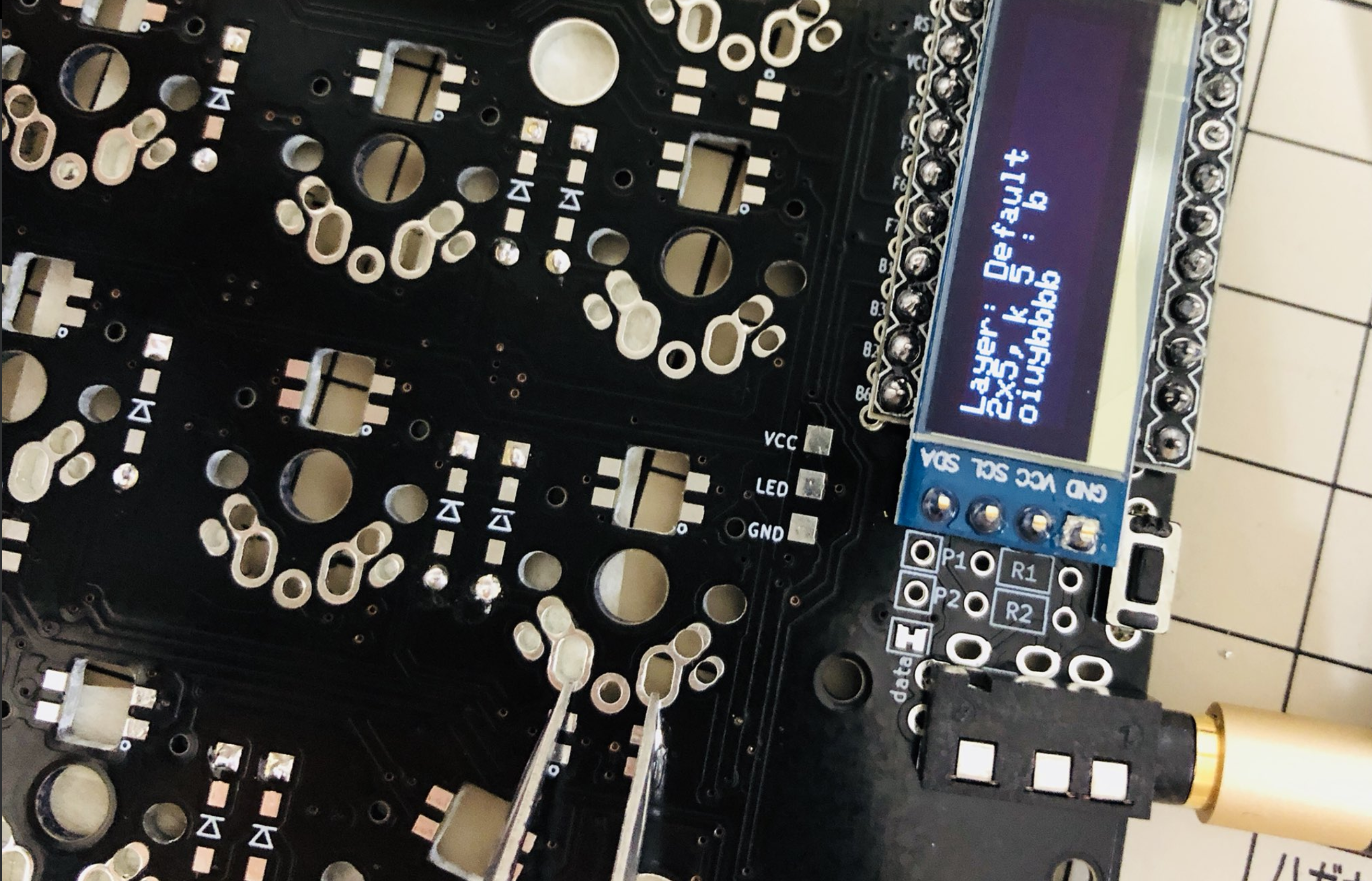
Using the default keymap, OLED will show information on the keyswitches being pressed. Check the connections by short-circuiting keyswitch soldering pads with tweezers or a bit of soldering wire. Check all of them.
If you have OLED displays,
you can verify that all keys are responding
by looking at the log information showed there.
It will say which row and column was pressed,
e.g. 1x5 or 0x2. Using the tweezers or wire,
connect each buttons soldering pads and make sure the display changes.
If something isn't working,
take note of the which row x column it is that isn't working,
as it can help when troubleshooting.
If you have mounted LEDs, also make sure all of them are turned on. As note before, the default firmware has LEDs turned off, so you have to turn them on in the firmware before you test.
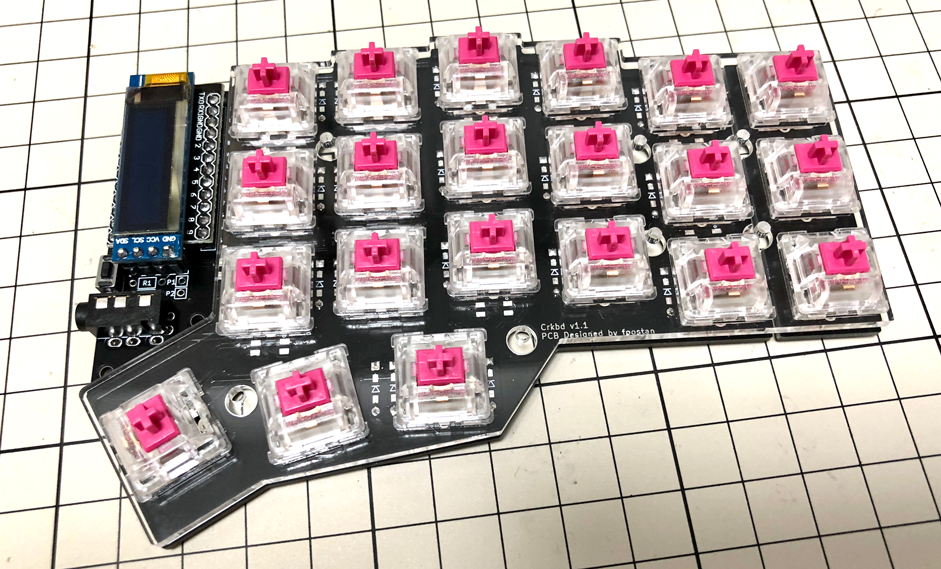
Keyswitches and Top Plate
Sandwich top-plate with PCB and key-switches.
Bottom Plate
Use 3mm spacers for low-profile, Attach bottom plate to the PCB using 7.5mm (3mm for low-profile) spacers. Then attach six rubber feet.
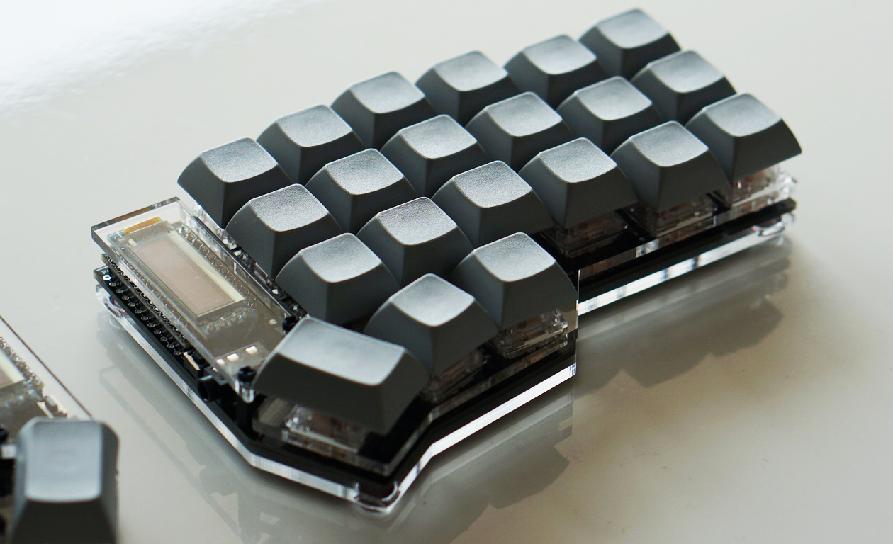
Keycaps
Lastly install keycaps.
Firmware
See below to flash the firmware to the ProMicro.
https://github.com/foostan/crkbd/blob/master/doc/firmware_en.md
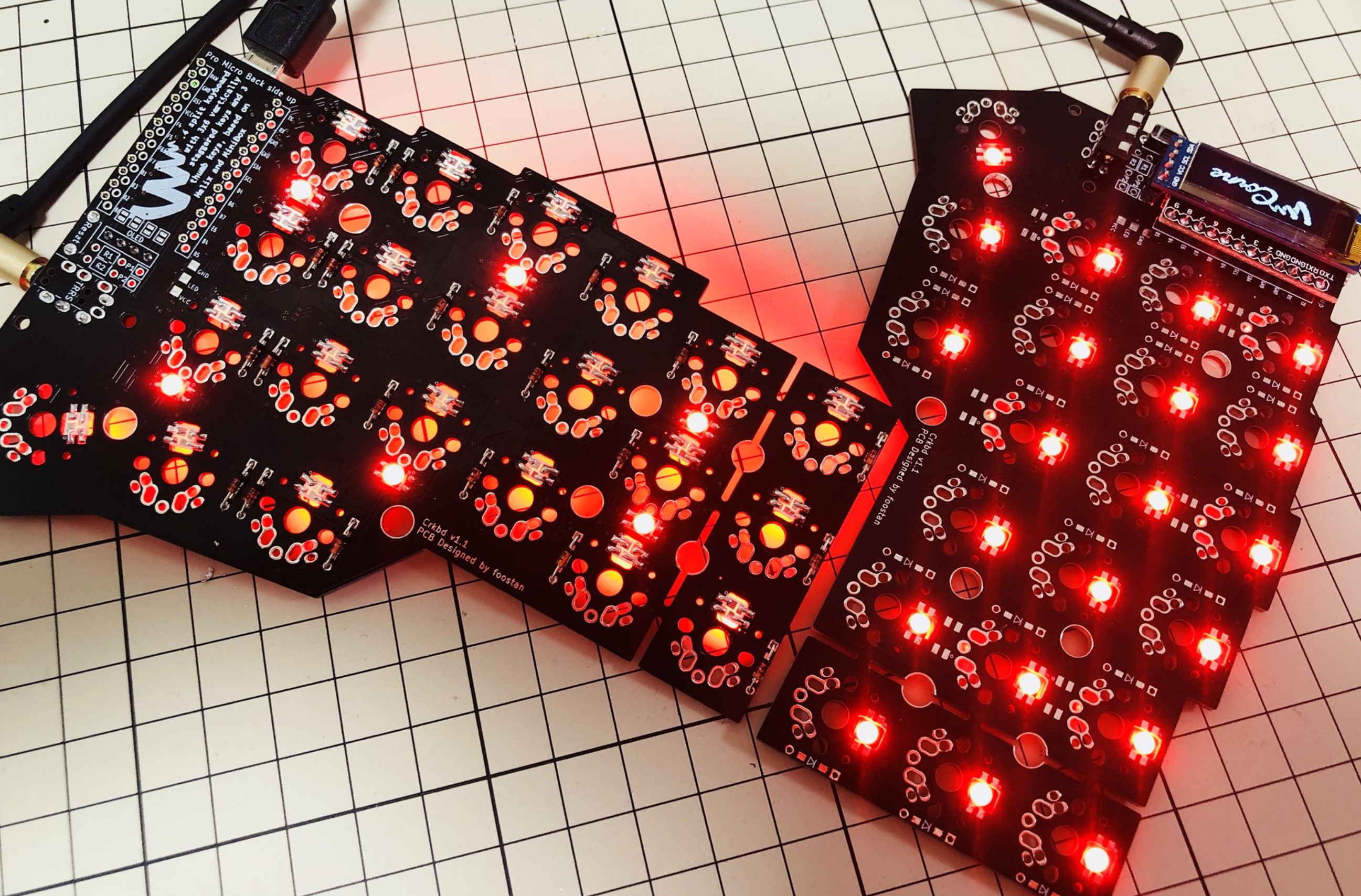
Turning LEDS on
To turn the LEDs on, you have to edit the rules.mk file.
If you use the default layout,
it can be found here keyboards/crkbd/keymaps/default/rules.mk.
Add the following line to the top of the file:
RGBLIGHT_ENABLE = yes
Compile and flash to both sides and all LEDs should turn on and glow red if you have soldered everything correctly. If you run the default firmware and the LEDs turn a differrent color, the data to the LEDs is probably corrupted somewhere along the way. Check the LED before the first one turning a different color using the troubleshooting guide below.
Troubleshooting
Here are some tips and tricks on how to troubleshot a board that is not working.
No LEDs turn on
There are a number of things that might be wrong. First of all, make sure you have turned on LED lighting in the firmware. If that is the case, then chances are there might be a problem with the first LED. Try the suggestions in the next section.
Some LEDs not turning on
If some LEDs aren't turning on, check the first LED not turning on or the one before it.
Here are some things to try out:
- Make sure the LED is soldered correctly. Check the pads to see if it looks like they have a proper connection.
- Check the LED orientation. Use the pictures above the see the correct orientation. Since the first LED is soldered with its back against the PCB, you might have to determinewhat the orientation should look like from the front using LEDs 7-27 (just double check that they are oriented correctly first).
- If both of the above looks good, chances are the LED was damaged during soldering. Either replace it directly or use the diod mode of a multimeter to test the connectivity. One way to do this is by simply comparing to some of the other LEDs you have soldered. Choose two of the LED's pads (out of the four available) and compare the reading to that of some of the other LEDs (taking care to measure the same pads with the same needles of your multimeter). Work your way through all combinations of pads and needles. If the differ, you either have a broken LED or bad connectivity. Or simply desolder the LED directly, might be quicker. :)
A full row/column of keys not working
If a full row or column of keys is not working, then the culprit is most likely the connection between the PCB and the ProMicro. Check your soldering and make sure there's a proper connection and that you have soldered the ProMicro in the right set of holes. If soldering looks okay, then your ProMicro might be damaged. You can exclude the possibility of problems with the PCB, paths and diodes by short circuiting the pins on the ProMicro directly, using a bit of wire. Connecting one row pin with one column pin should result in the corresponding key. Some PCBs have silkscreen print indicating which pin is which row or column, to make this process easier.
Random key(s) not working
If it is not a full row or column of keys that are not working, the issue is most likely that there's no connection between the key and the ProMicro. There are multiple places where the connection can get interupted:
- between keyswitch and PCB (if you have installed the switches)
- between keyswitch and hotswap socket (if you use them)
- between hotswap socket and PCB (again, if you use hotswap sockets)
- in the diodes between the key and the ProMicro
- in the paths inside the PCB
If you have installed the keyswitches already, then check the soldering on the keyswitch. if you use hotswap sockets, check that you didn't accidentally bend one of the legs of the switch when inserting into the socket and that the socket soldering is alright.
Next, visually inspect the PCB. If it looks scratched or damaged anywhere along the path from ProMicro to diode to keyswitch, the path might be interrupted. If you find a spot that looks damaged, you can use some wire to bypass the section that is damaged (e.g. connecting the ProMicro directly to the first pad of the diode). If this fixes the key, then you can either opt to keep the wire permanently, or you can try to repair the path. The path can be repaired by carefully scraping off the paint from a section of the path that is okay on either side of the damaged part (use a small flat head screwdriver intended for electronics). Then clean carefully with alcohol and solder a new connection. Youtube might have some guides on how to do this.
If the PCB looks okay, then the diode would be the next thing to check. Begin by checking the soldering. If it looks okay, then the diode itself might be damaged. If you have a multimeter, use it to check the diode. The reading should be the same as for diodes connected to keys that are working (when measuring, remember that diodes have polarity). You can also use tweezers or a bit of soldering wire to connect the soldering pads on each side of the diode if you don't have a multimeter. Pressing the key (or short circuiting the pads where the key would go) after connecting the pads should make a key press being registered. If this is the case, or if you used the multimeter and got a different reading from the diode, then check your soldering and replace the diode if necessary.