7.5 KiB
Build Guide
This is the Corne Light v1 build guide.
Parts
Advance preparation
If you build the firmware yourself,
it takes time to prepare the environment,
so it is recommended to start first.
See https://github.com/foostan/crkbd/blob/master/doc/firmware_en.md
for more information.
Implementation
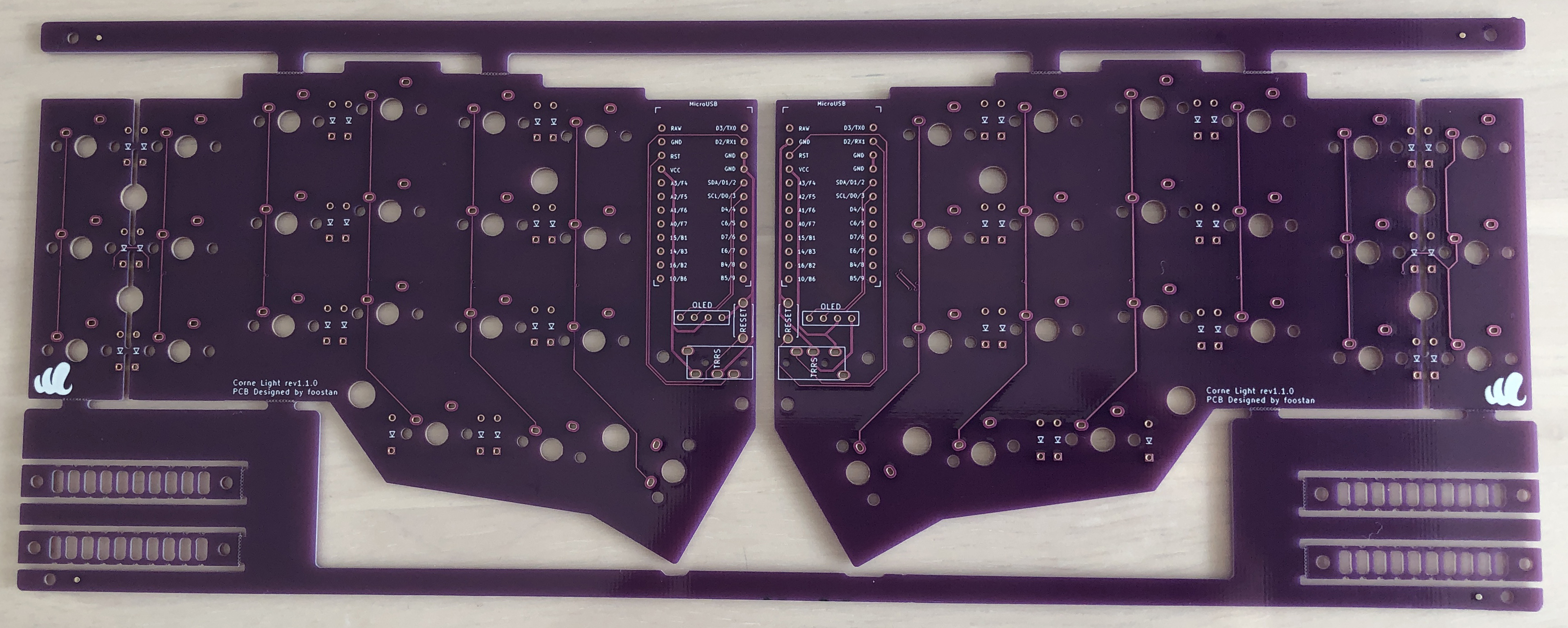
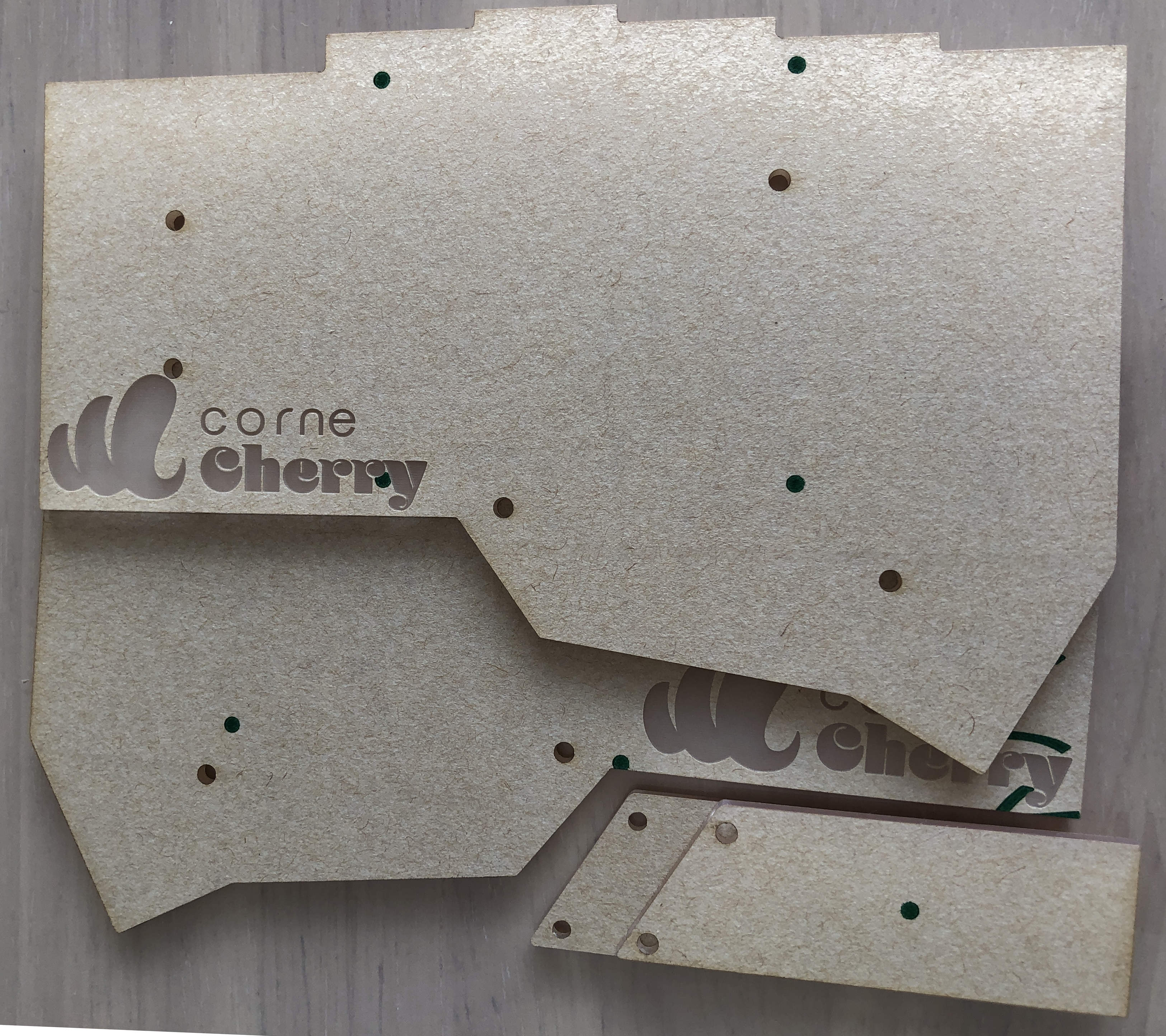
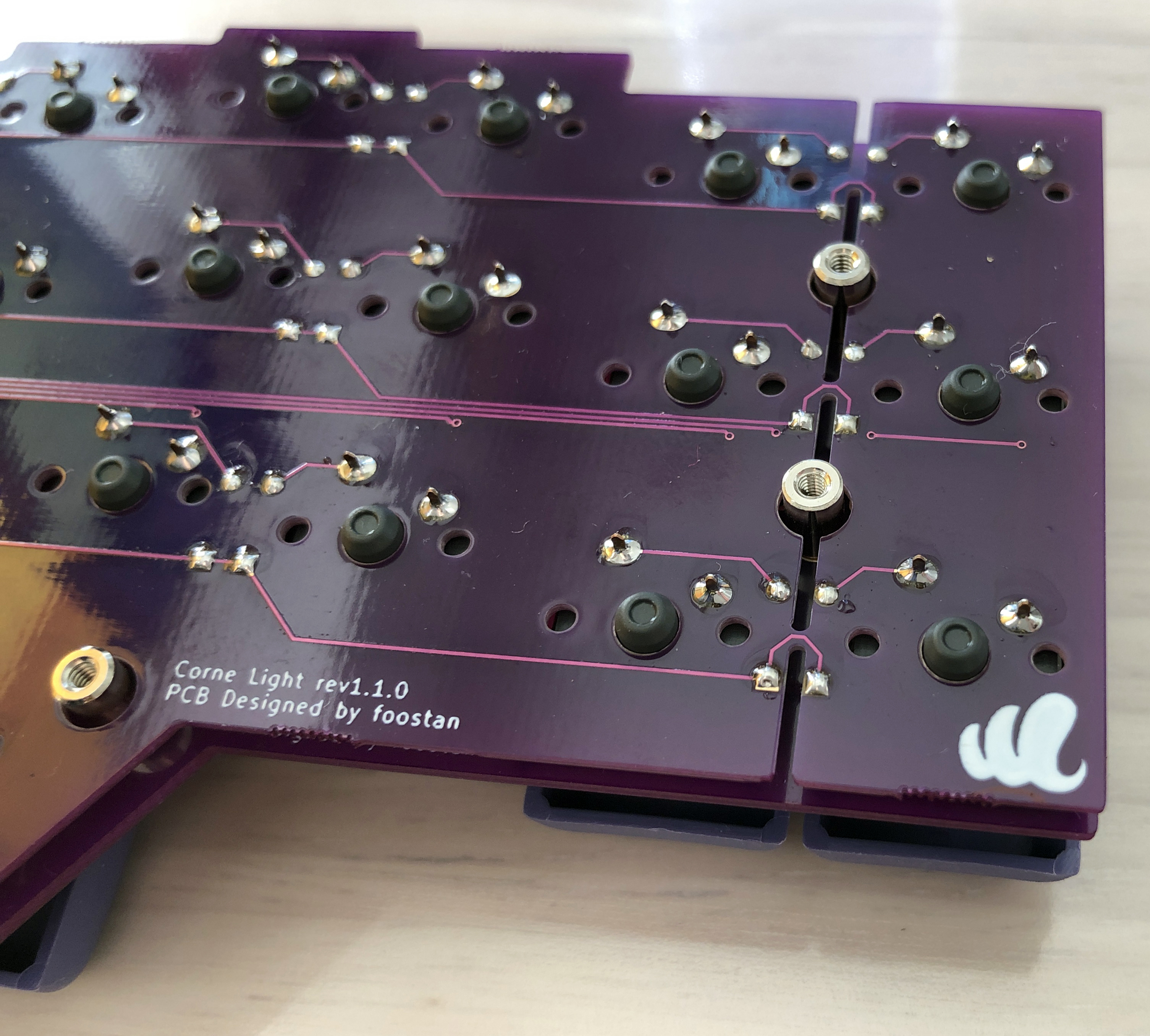
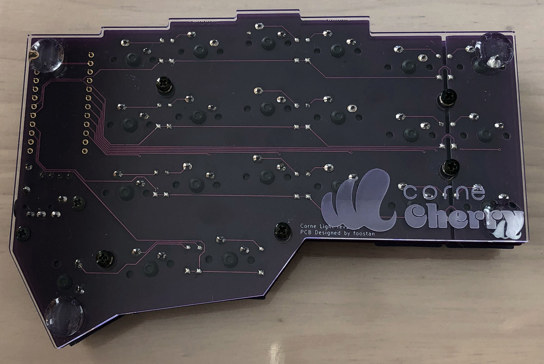
PCB disconnection
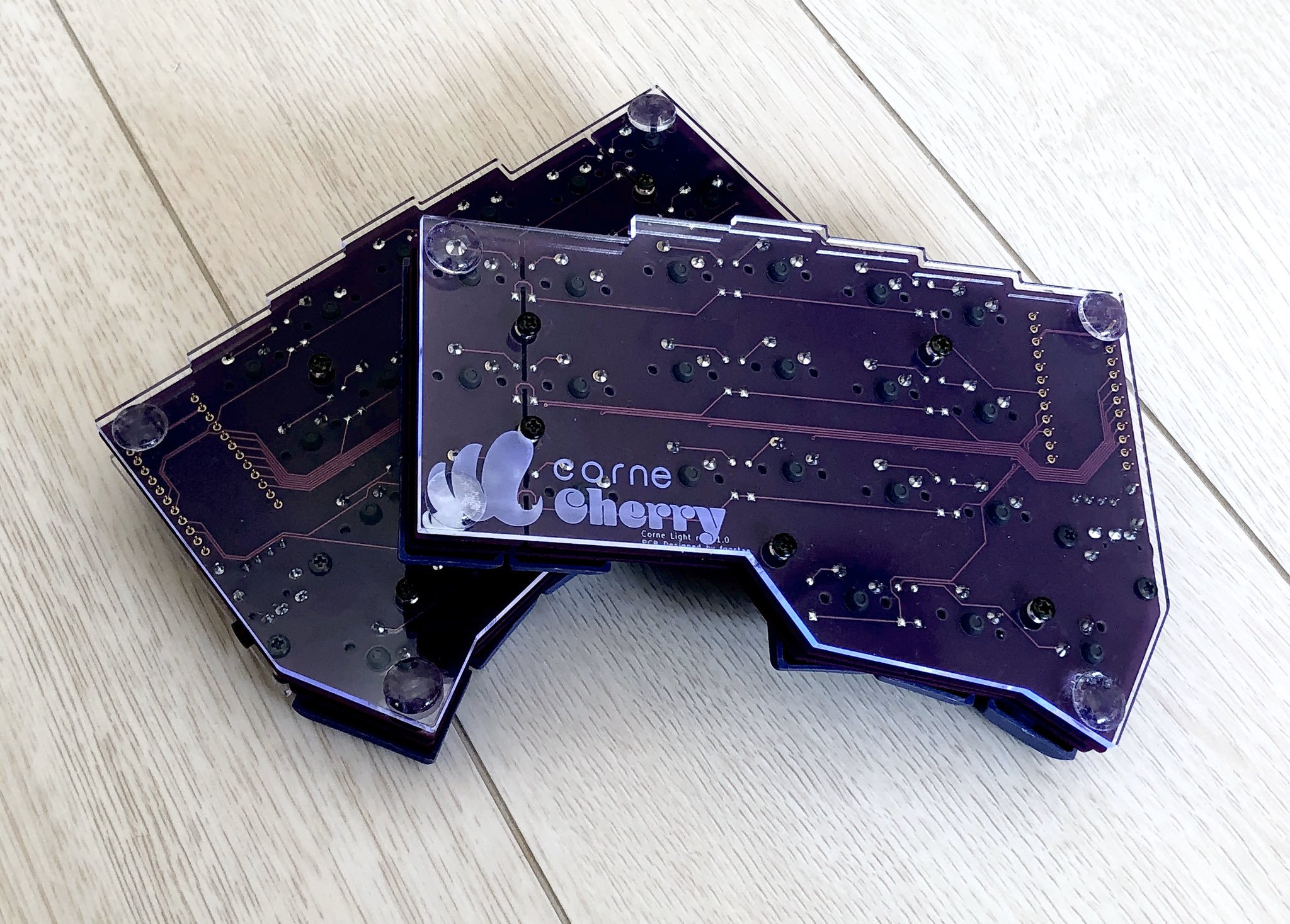
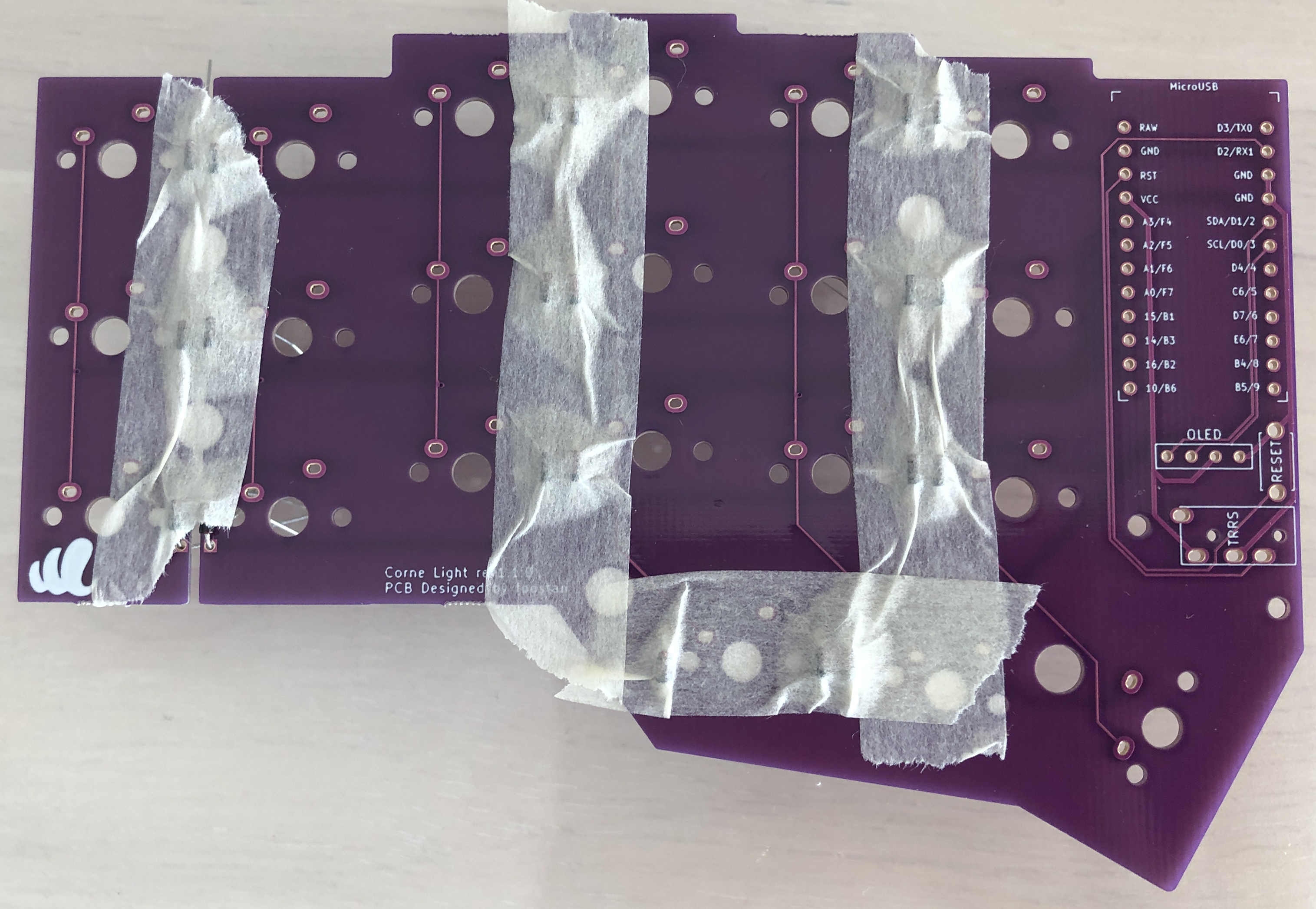
Check the front and back and separate the left and right PCBs (the photo is the front).
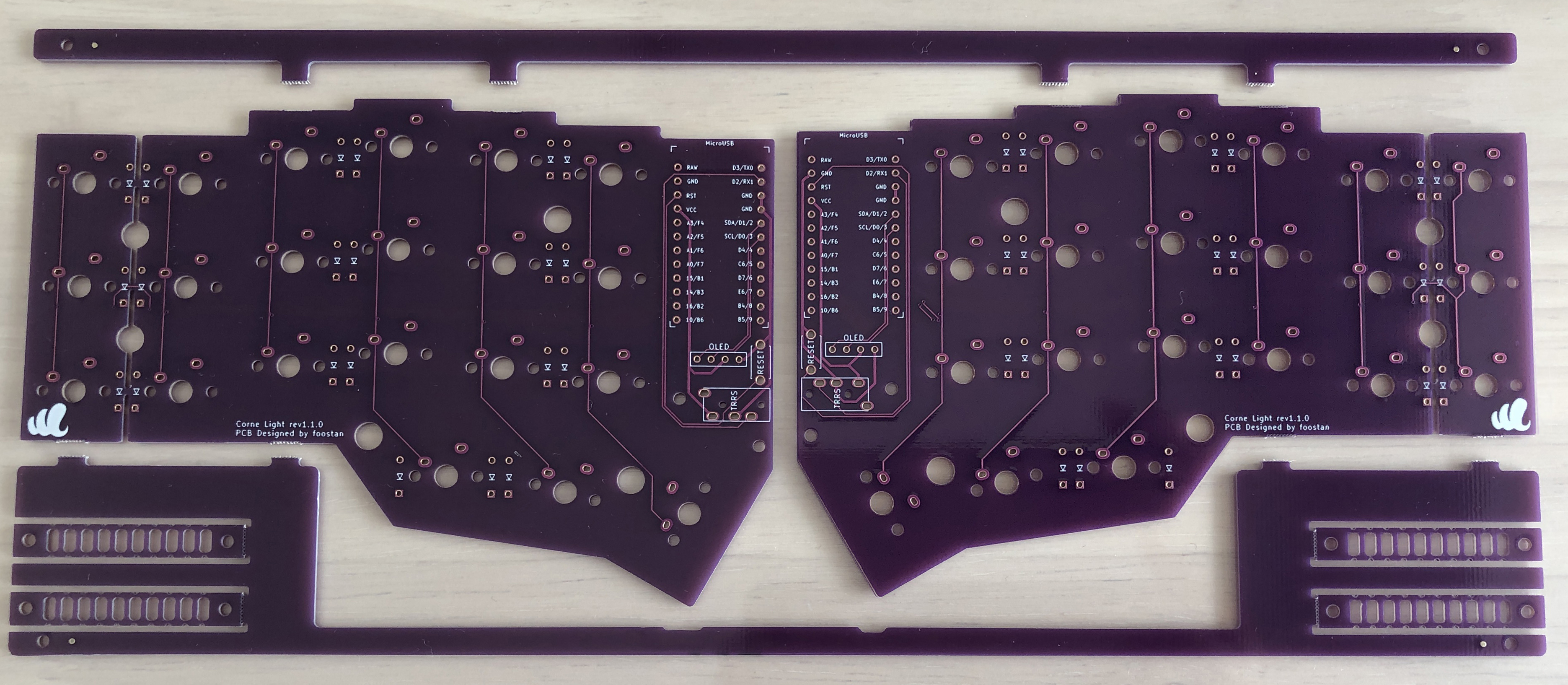
This is a jig for bending the legs of a diode. Separate it if necessary.
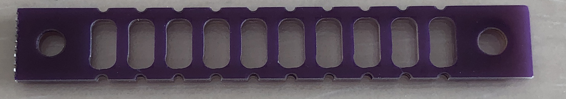
- Some versions do not have a jig.
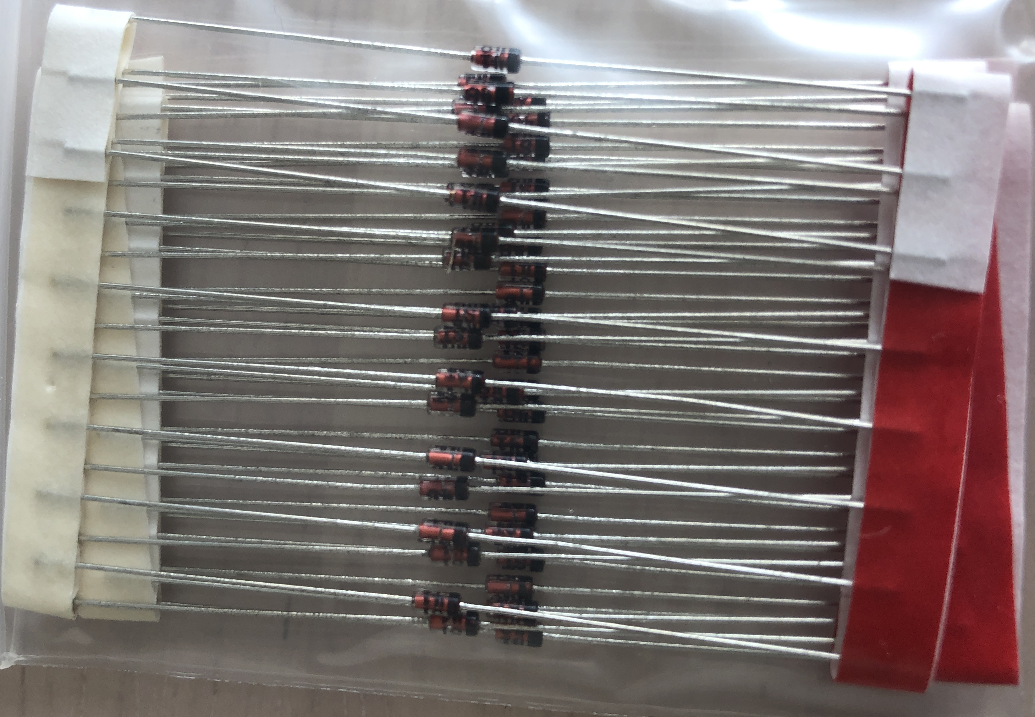
Diodes
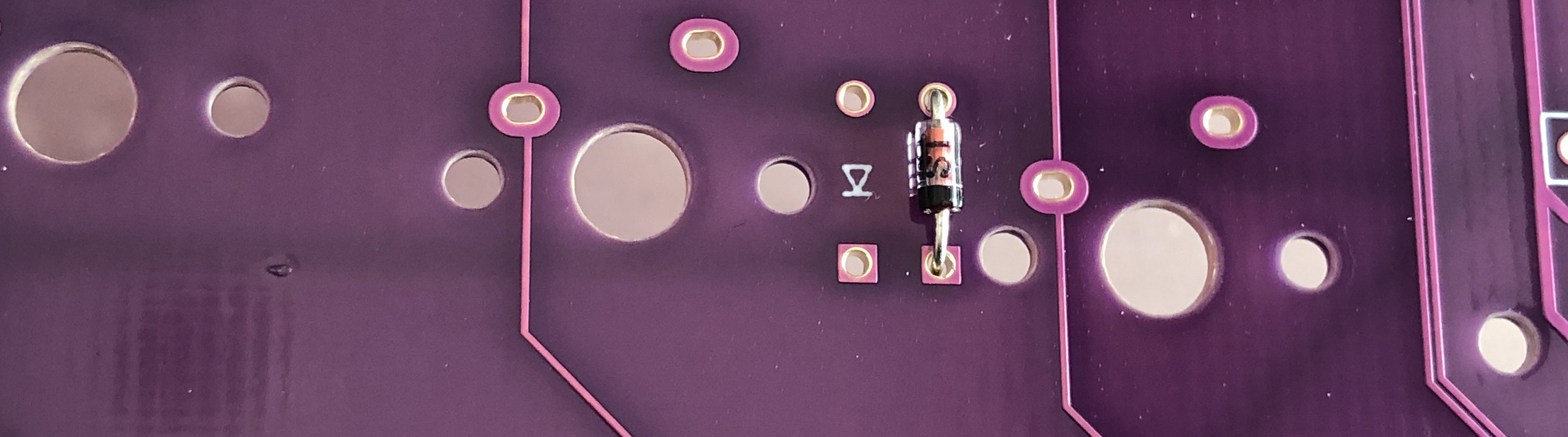
First, bend the legs of the reed type diode.
- You can clean it by bending it one by one as shown in the picture, but it is more efficient to bend multiple pieces at the same time while connected to the tape.
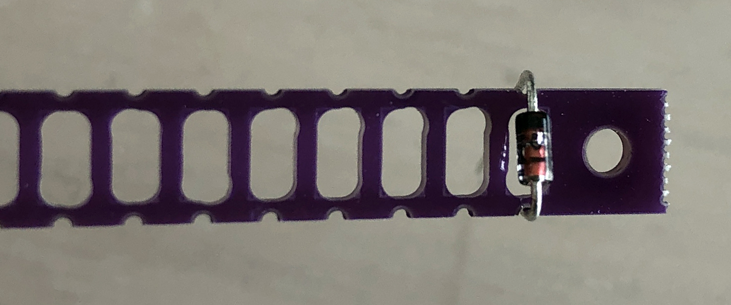
Attach the diode with the bent leg to the specified position.
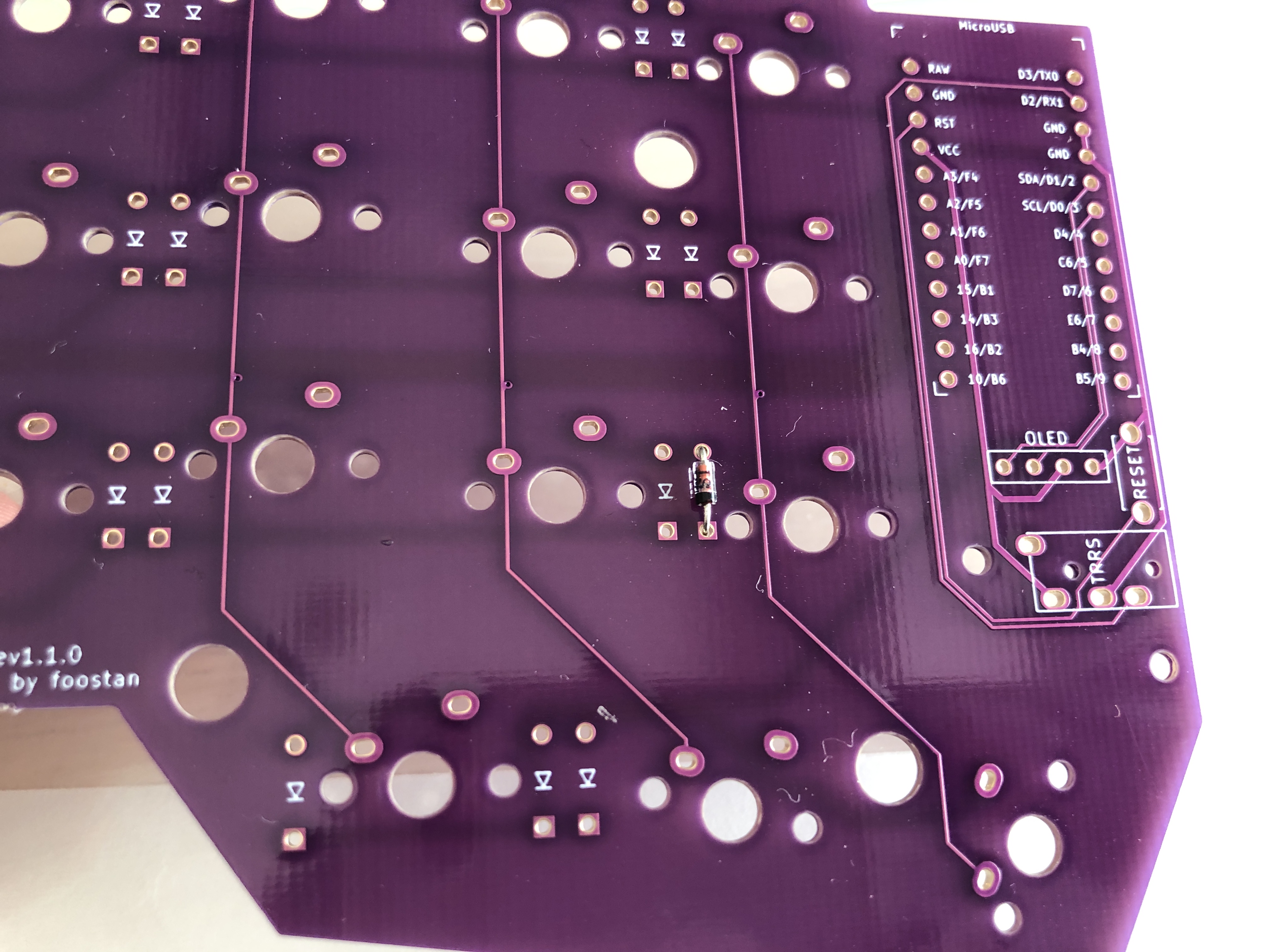
The diode has an orientation and is installed as shown in the photo.
- All the diodes to be attached are in the same orientation.
You can attach it neatly by fixing it with masking tape.
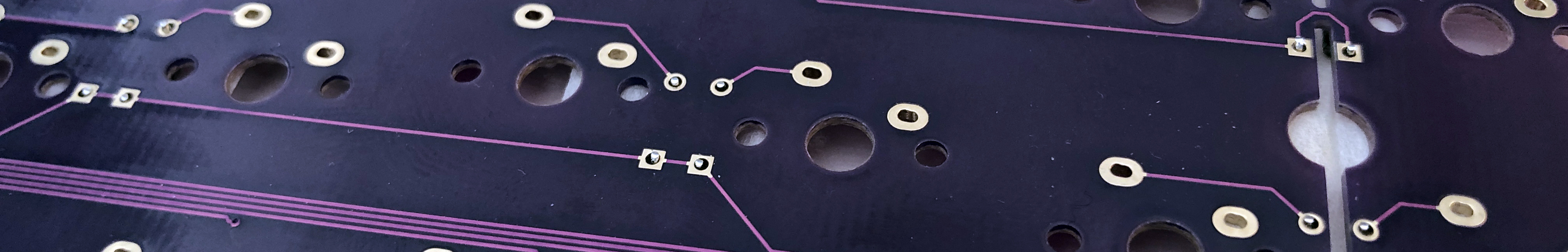
Solder from the back side.
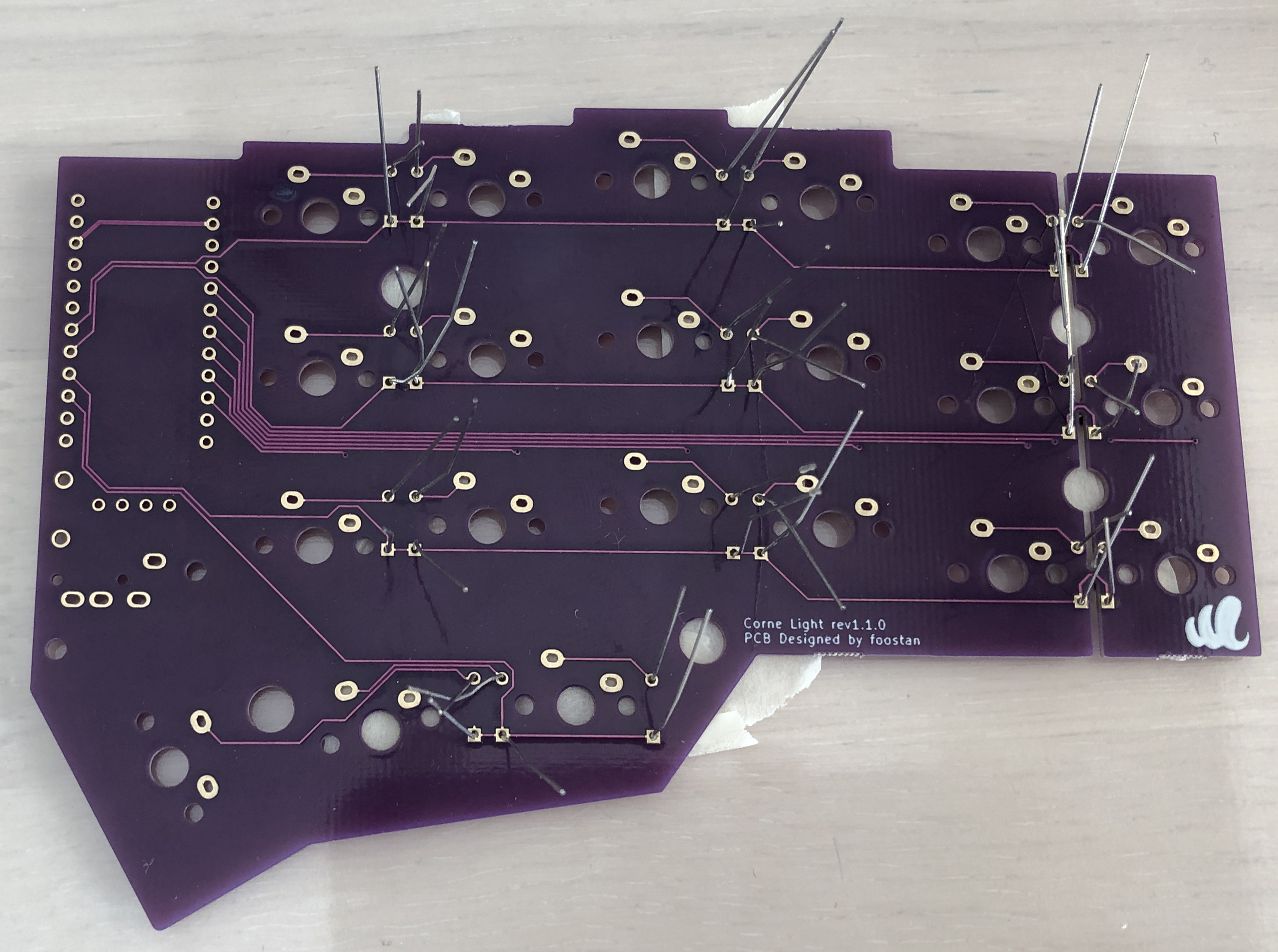
If you are fixing with masking tape, cutting your legs to the limit like this will make soldering easier.
With 21 one-handed and two-handed he installs 42 diodes.
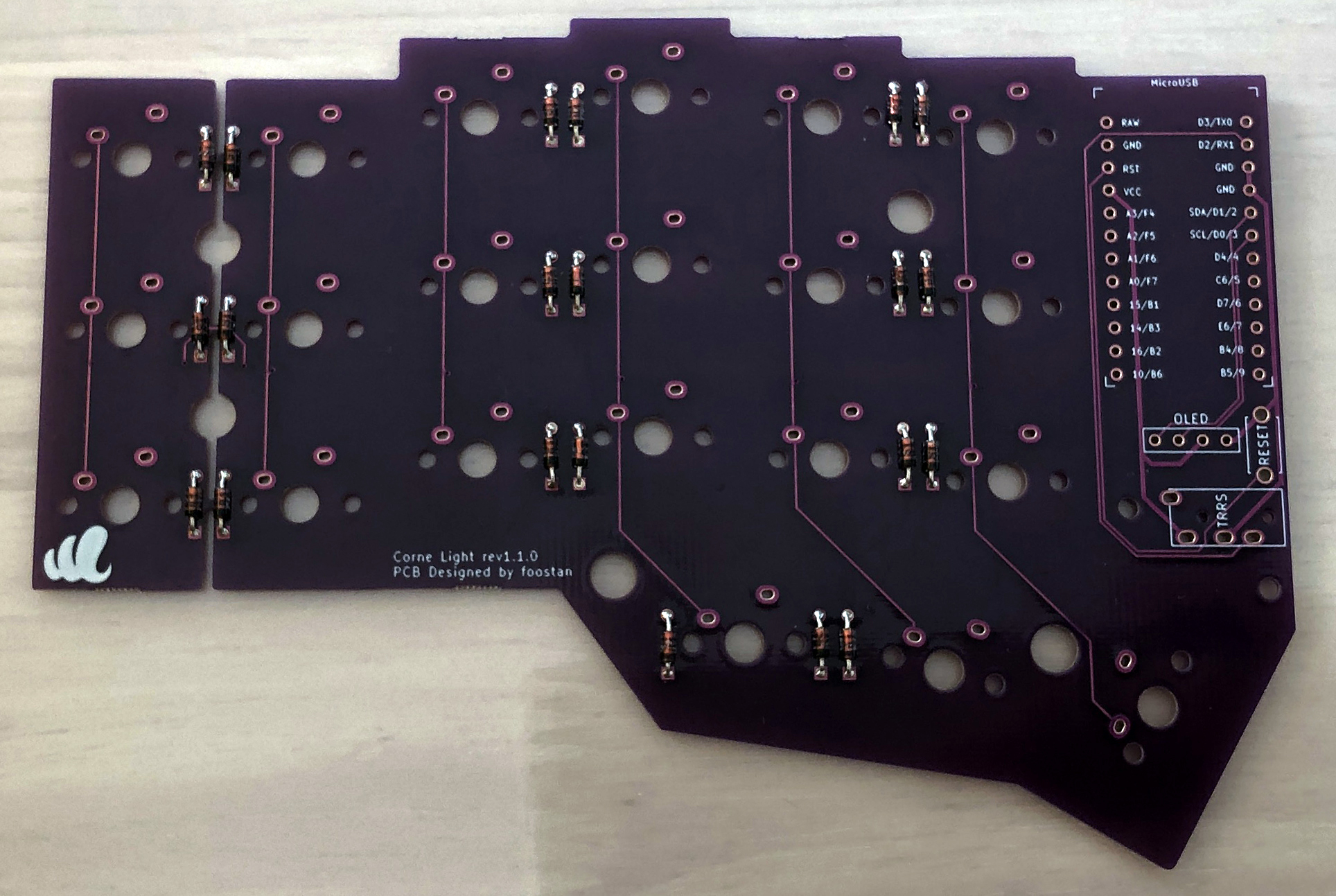
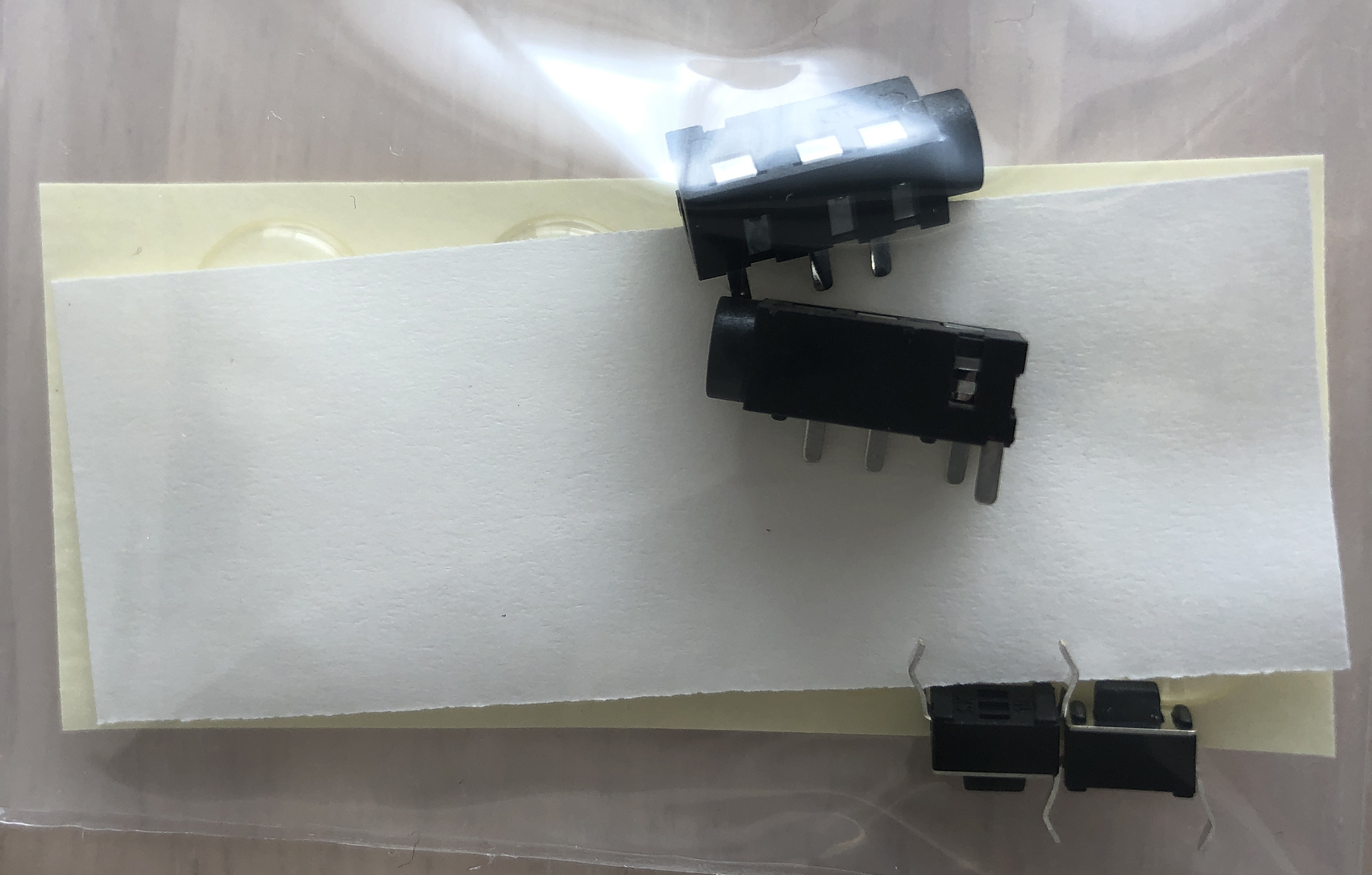
TRRS jack, reset switch, pin socket
Install in the specified position.
- Install the right hand side in the same position (be careful of mistakes on the front and back).
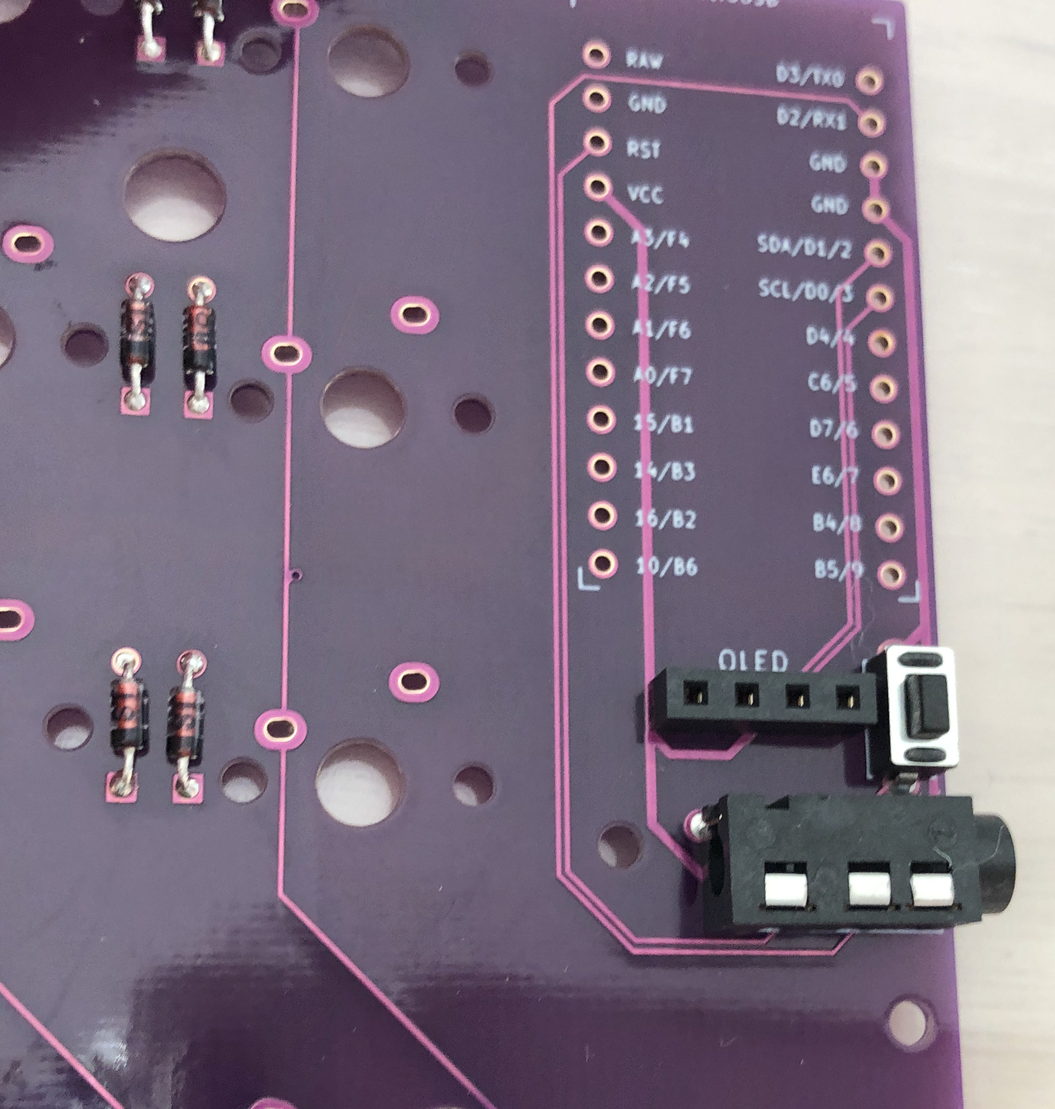
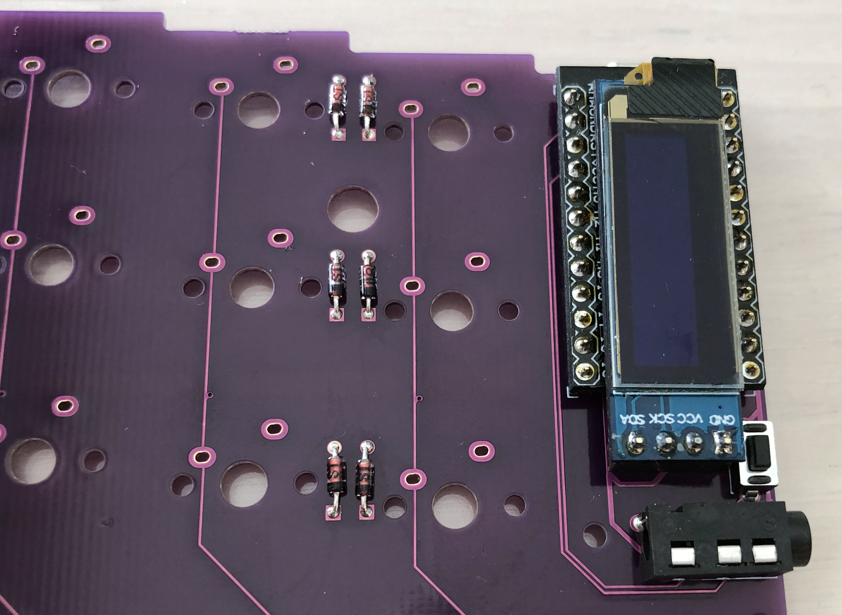
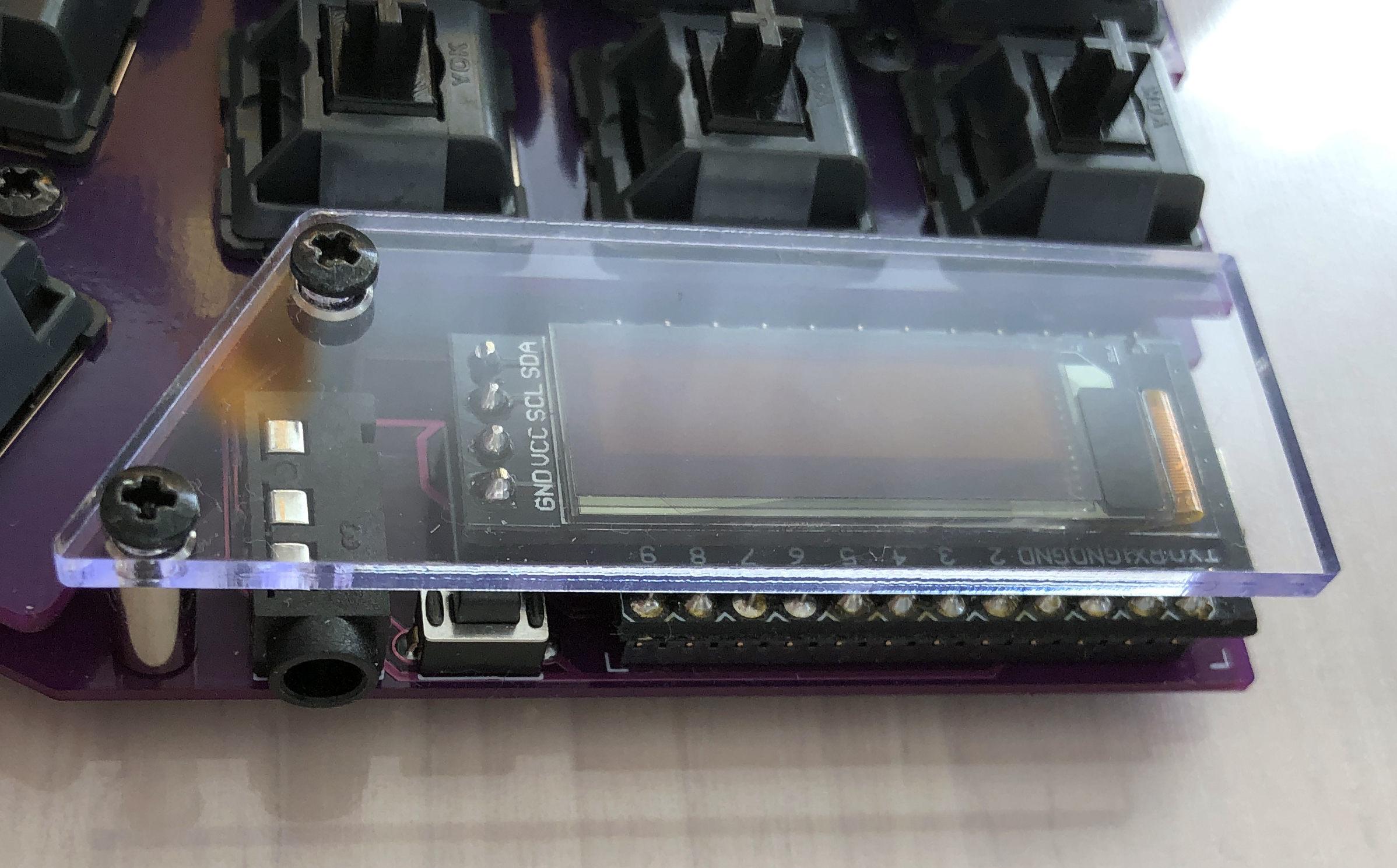
ProMicro, OLED module
Install his ProMicro and his OLED module by referring to the Helix Build Guide.
Firmware
Write the firmware to ProMicro by referring to the following.
https://github.com/foostan/crkbd/blob/master/doc/firmware_en.md
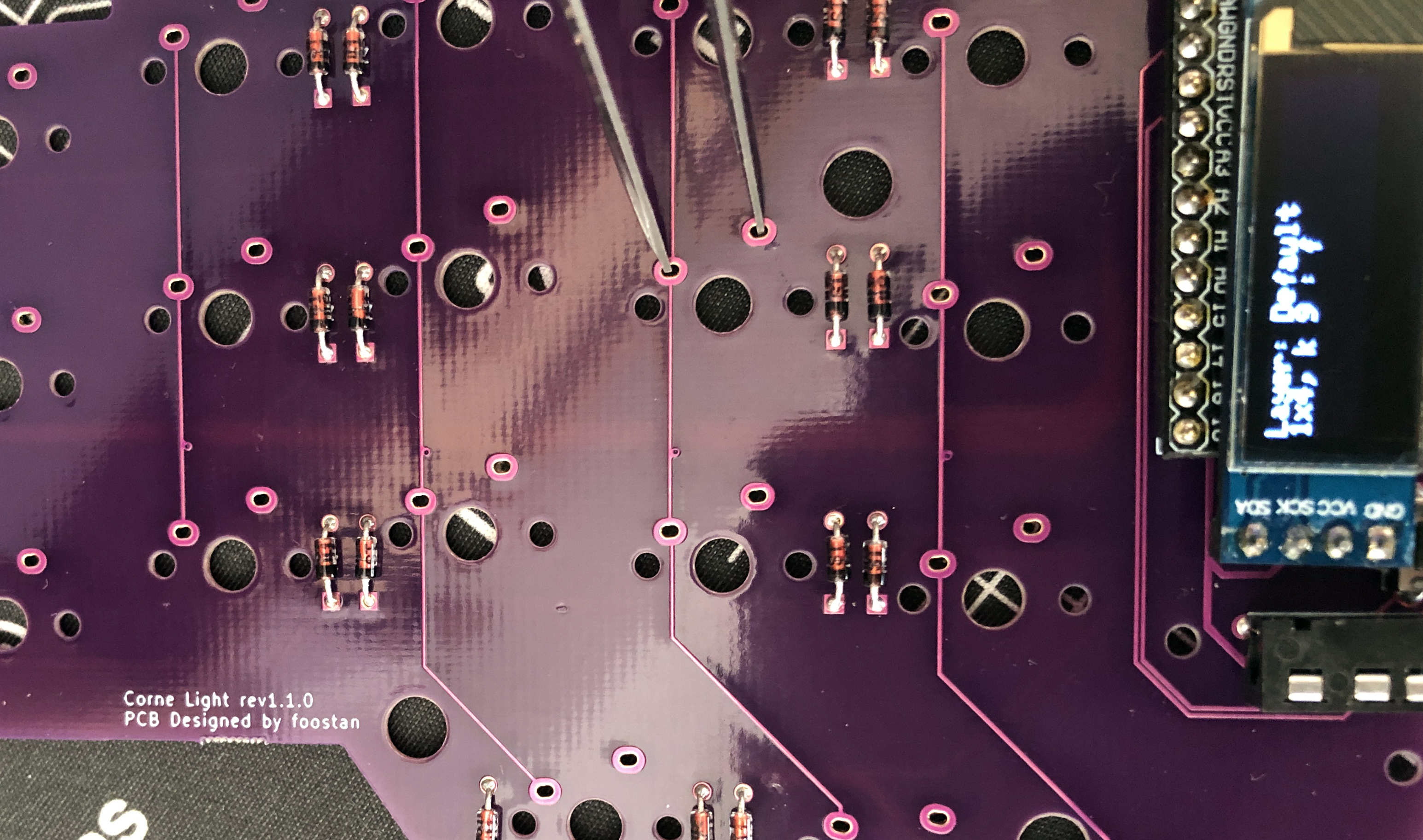
Operation check
To check the operation, connect the left hand side to the PC with a USB cable, and connect the left hand side and the right hand side with the TRRS cable. Since there may be defects such as jacks, be sure to connect the left and right instead of one by one before checking the operation.
- Since the switch is not attached, check the operation with tweezers as shown in the photo.
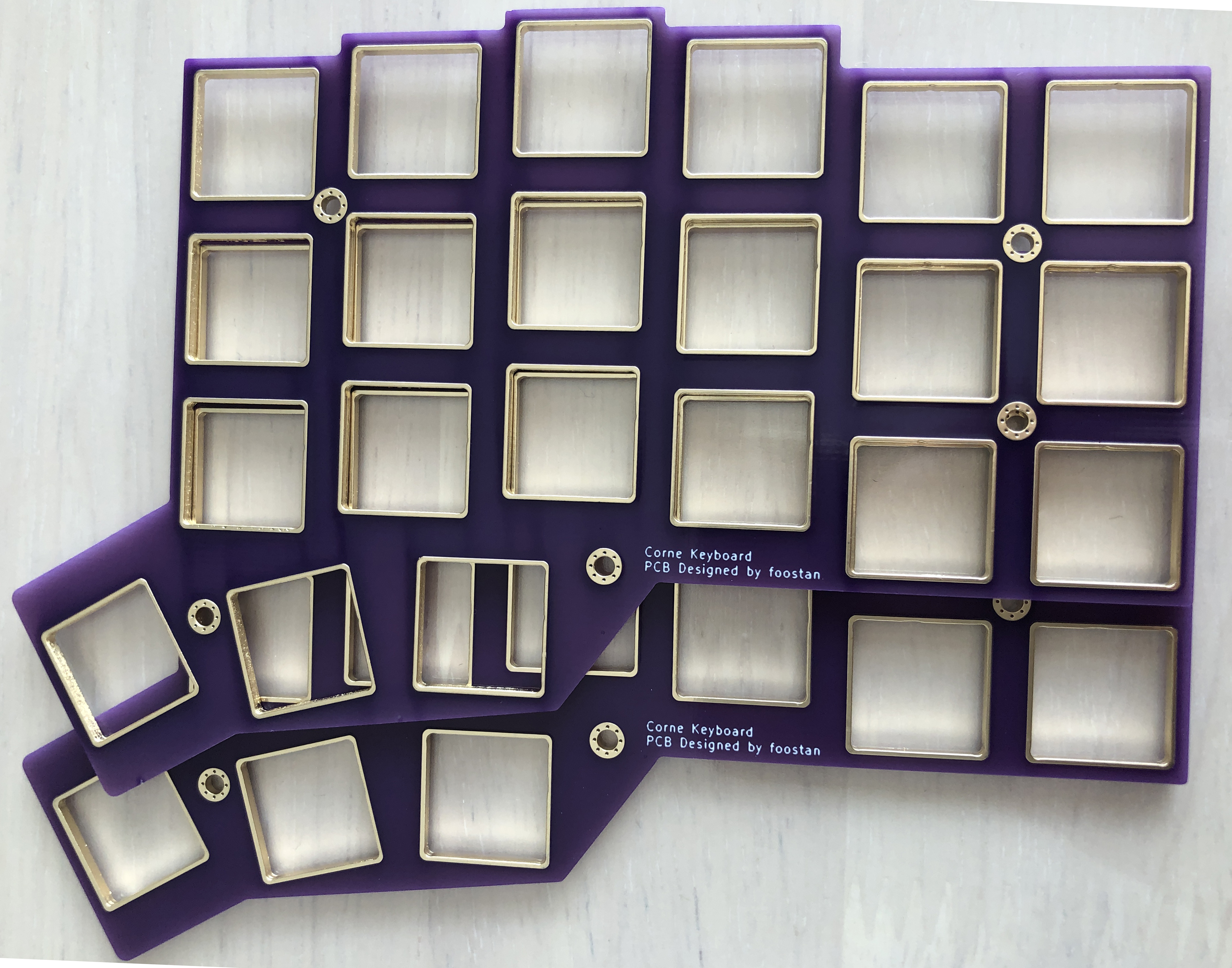
Top plate, key switch
Attach the key switch to the top plate as shown in the picture.
- Be careful of the direction of the key switch.
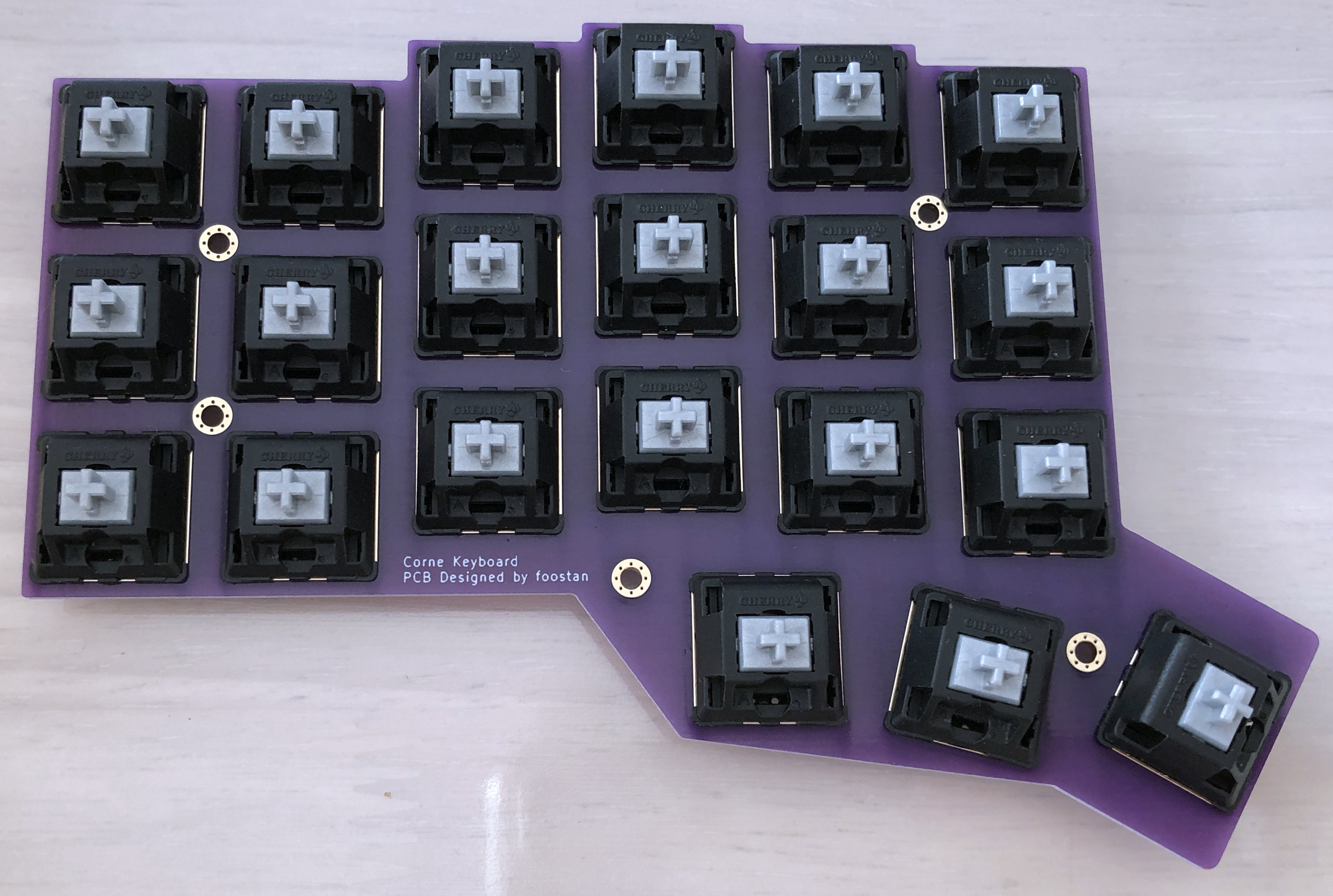
We recommend using a 3-pin key switch.
- Even when using 5 pins, the plastic legs can be separated to make 3 pins.
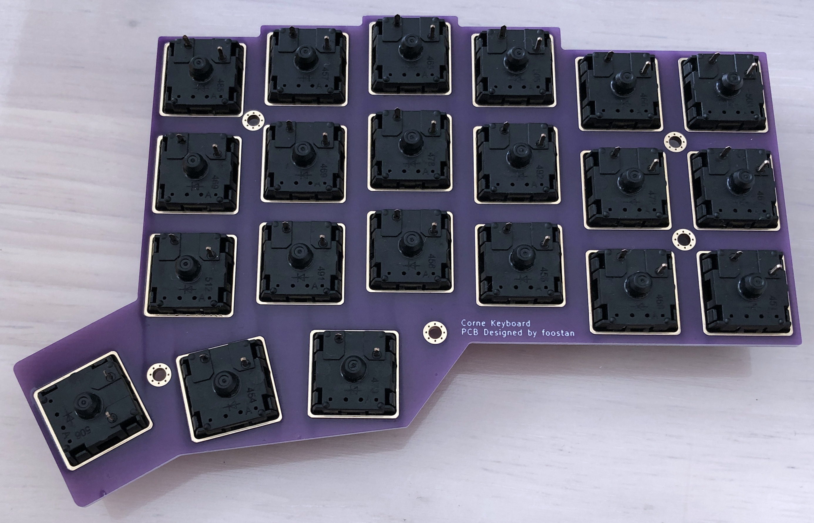
Solder so that there is no gap between the switch and the PCB.
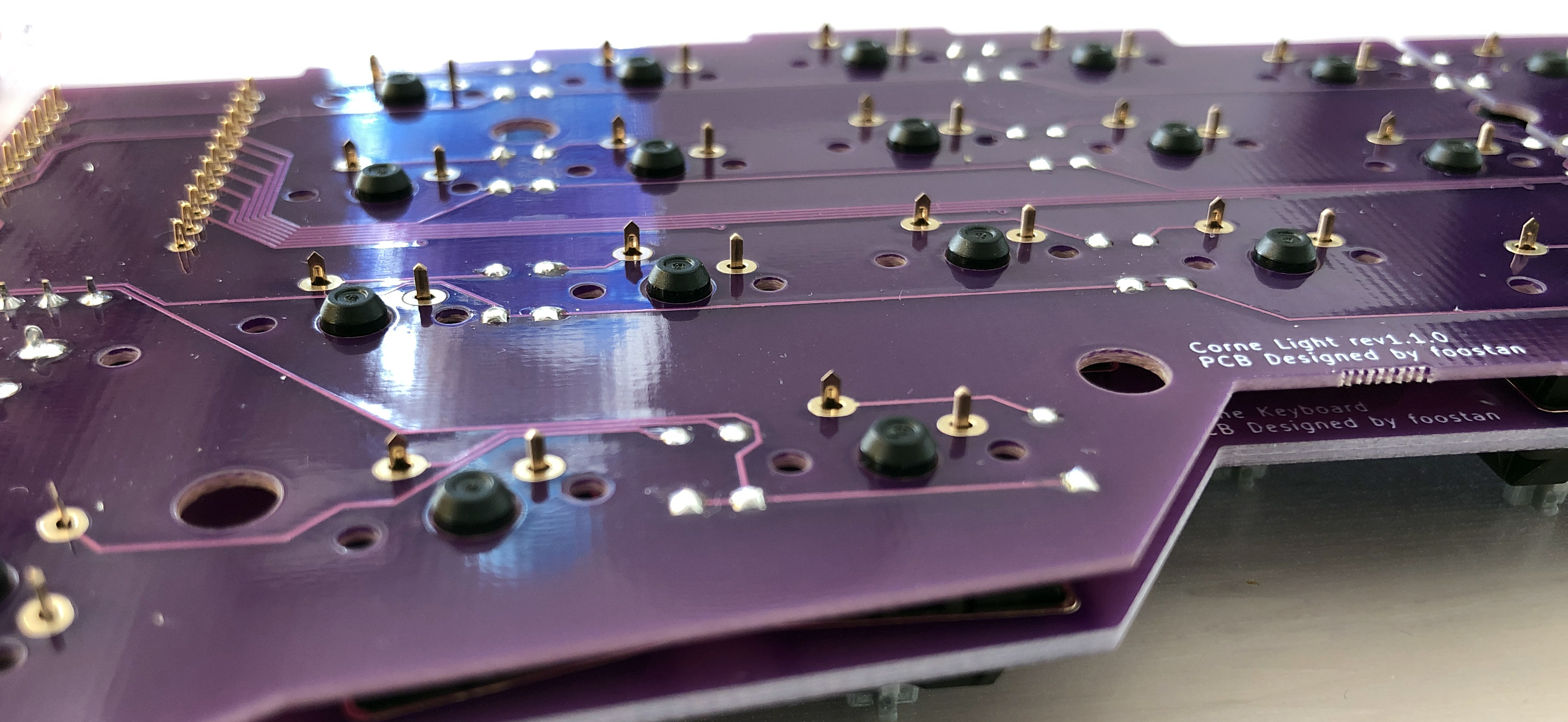
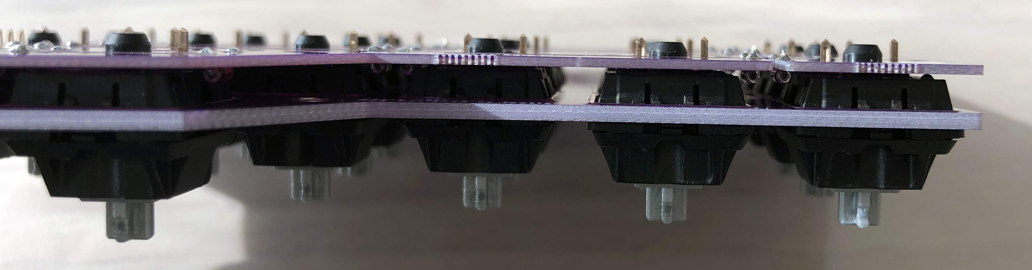
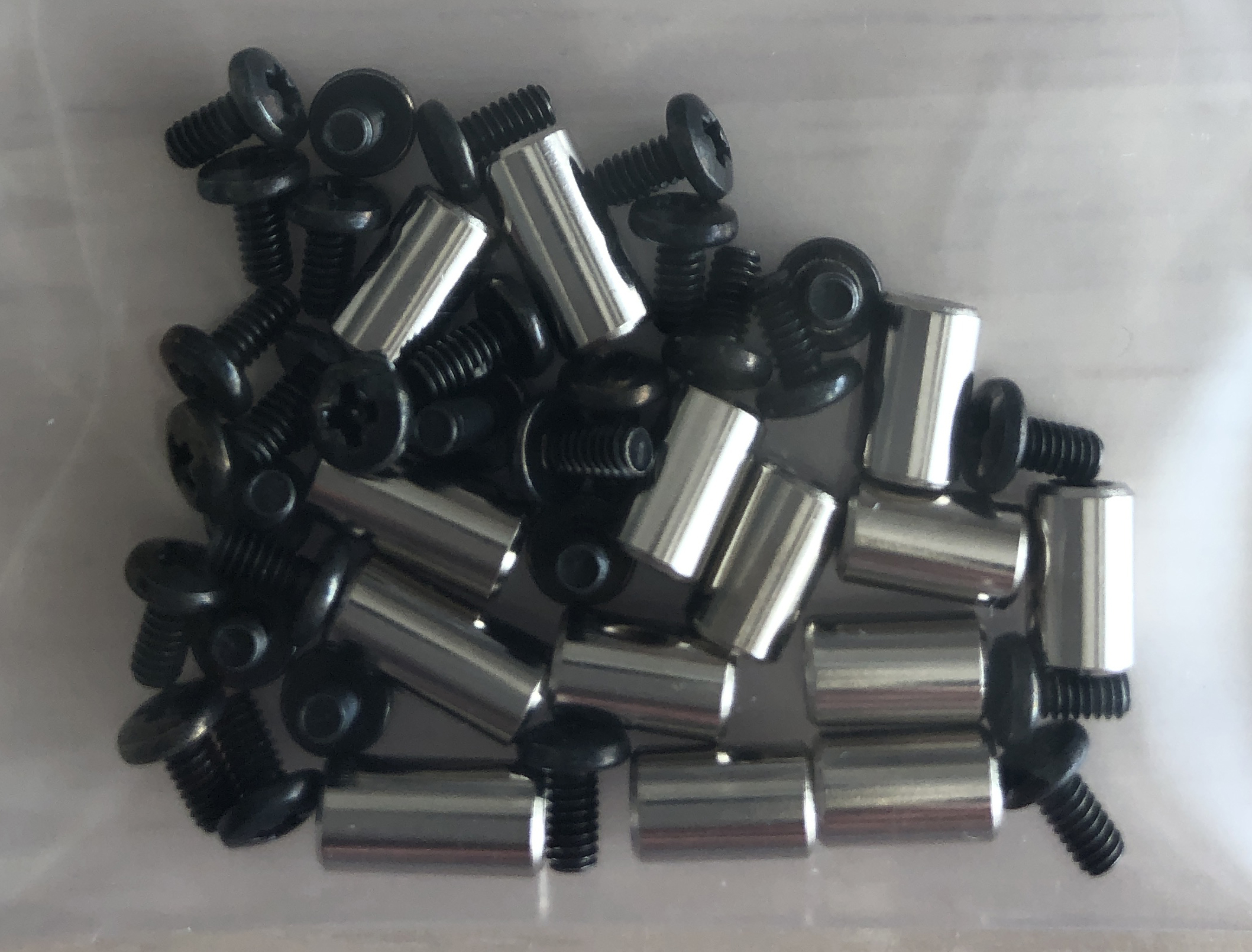
ProMicro Protective Plate, Bottom Plate
Attach his ProMicro protective plate using an M2 9mm spacer.
Install the bottom plate using the M2 7.5mm spacer.
Attach the rubber feet to the four corners.
Complete
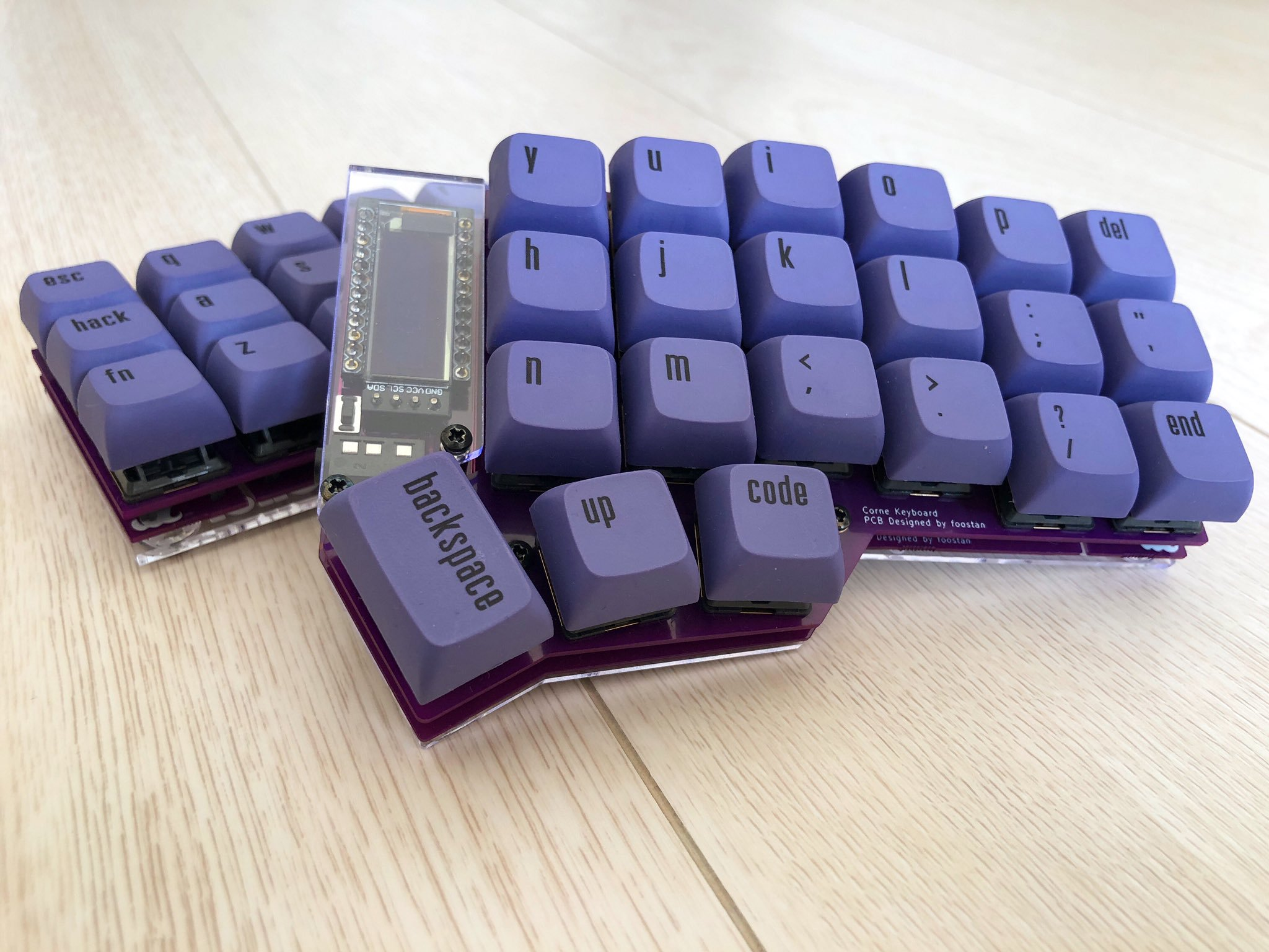
Attach the keycap and you're done.