mirror of https://github.com/foostan/crkbd.git
209 lines
6.8 KiB
Markdown
209 lines
6.8 KiB
Markdown
# Build Guide
|
|
|
|
This is the build guide for Corne Light v2 Low edition.
|
|
|
|

|
|

|
|

|
|
|
|
## Parts
|
|
|
|
### Required
|
|
|
|
| Name | Count | Remarks |
|
|
|:-|:-|:-|
|
|
| PCB | 1 set | |
|
|
| Top plate (acrylic) 2mm | 2 sheets | |
|
|
| Bottom foam | 2 sheets | Special foam is cut out with a special mold |
|
|
| OLED protective plate | 2 sheets | |
|
|
| ProMicro | 2 sheets | |
|
|
| TRRS jack | 2 | |
|
|
| Tact switch | 2 | |
|
|
| Diodes | 42 | Recommended SMD Parts |
|
|
| Key switches | 42 | Kailh Choc v1 or v2 recommended |
|
|
| Keycaps | 42 pcs | 1u 40 pcs, 1.5u 2 pcs |
|
|
| Spacer M2 9mm | 4 pieces | |
|
|
| Screw M2 4mm | 8 screws | |
|
|
| TRRS (4 poles) cable | 1 | TRS (3 poles) cable is also acceptable |
|
|
| Micro USB cable | 1 | |
|
|
|
|
### Optional
|
|
|
|
| Name | Count | Remarks |
|
|
|:-|:-|:-|
|
|
| OLED module | 2 sheets | |
|
|
| Pin header for OLED module 4 series 1.5mm | 2 | |
|
|
| 4 pin sockets for OLED module 2.5mm | 2 | |
|
|
|
|
## Advance preparation
|
|
|
|
If you build the firmware yourself,
|
|
it takes time to prepare the environment,
|
|
so it is recommended to start first. \
|
|
See <https://github.com/foostan/crkbd/blob/master/doc/firmware_en.md>
|
|
for more information.
|
|
|
|
## Verification
|
|
|
|
The PCB for Corne Light v2 is as follows.
|
|
Make sure it is the same as your PCB.
|
|
|
|

|
|
|
|

|
|
|
|
The PCB comes with a frame for manufacturing reasons.
|
|
You can fold it by hand to remove it, but if it is difficult,
|
|
make a cut in the joint \* with a cutter or similar,
|
|
to make it easier to remove.
|
|
In addition, the joint can be cleaned with a file.
|
|
|
|
\* *Joint part: There are a total of 8 parts,
|
|
which are marked in red in the image below.*
|
|
|
|

|
|
|
|
## Assembly
|
|
|
|
### Diodes
|
|
|
|
Solder diodes for SMD components.
|
|
Since SMD parts are very small,
|
|
it is convenient to have tweezers and counter-acting tweezers.
|
|
|
|
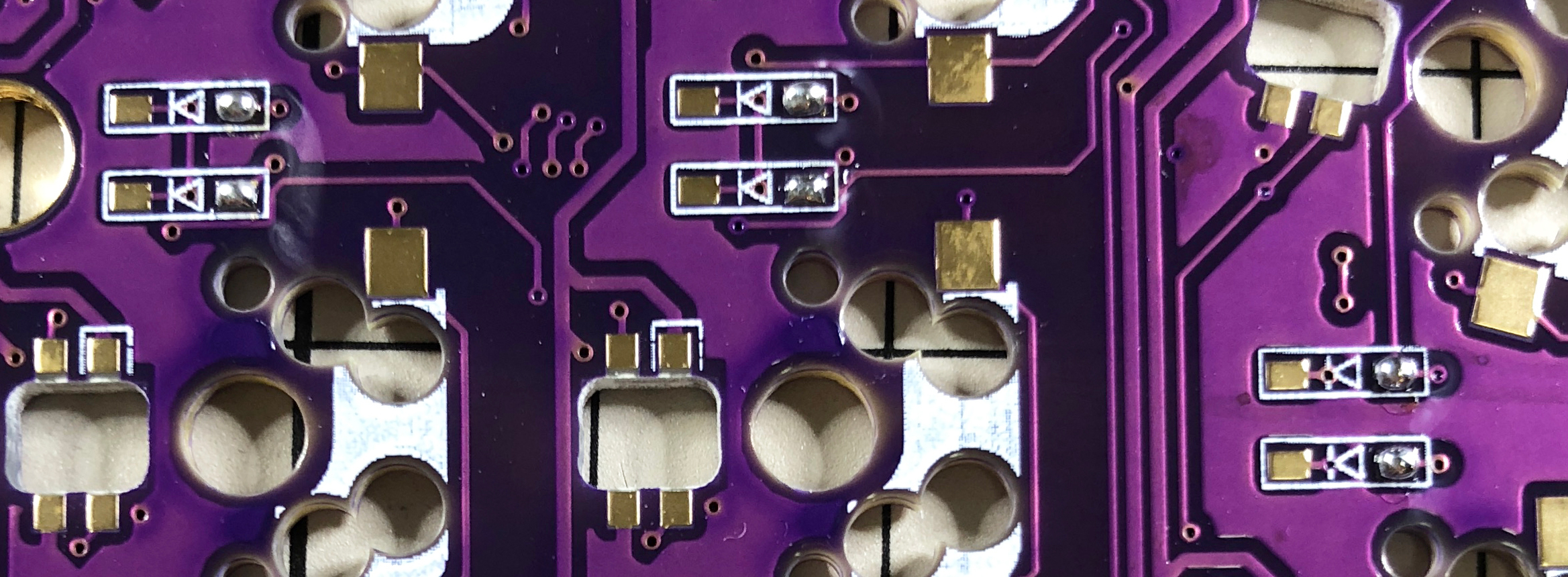
**The diode has a fixed mounting direction**,
|
|
so solder it so that the "|" mark on the part faces the "|" on the diode mark "|◁".
|
|
In addition, Corne's PCB has all the same diode mounting orientations.
|
|
|
|

|
|
|
|
<details>
|
|
<summary>TIPS: Tips for installing SMD parts</summary>
|
|
|
|
The trick is to attach the SMD parts, but first, as a spare solder,
|
|
put the solder on only one side of the pad.
|
|
|
|
|
|
|
|
Next, solder one leg of the diode so that the spare solder melts.
|
|
At this time, it is recommended to use reverse-action tweezers,
|
|
because you can hold the chip parts firmly without exerting force
|
|
and you can concentrate on alignment and soldering.
|
|
Also, if the soldering iron is too hot or the solder is touched too much,
|
|
the flux contained in the solder may evaporate and form a clean pile of solder,
|
|
but it can be repaired later,
|
|
so at this point you should only care about attaching parts.
|
|
It's okay.
|
|
|
|
|
|
|
|
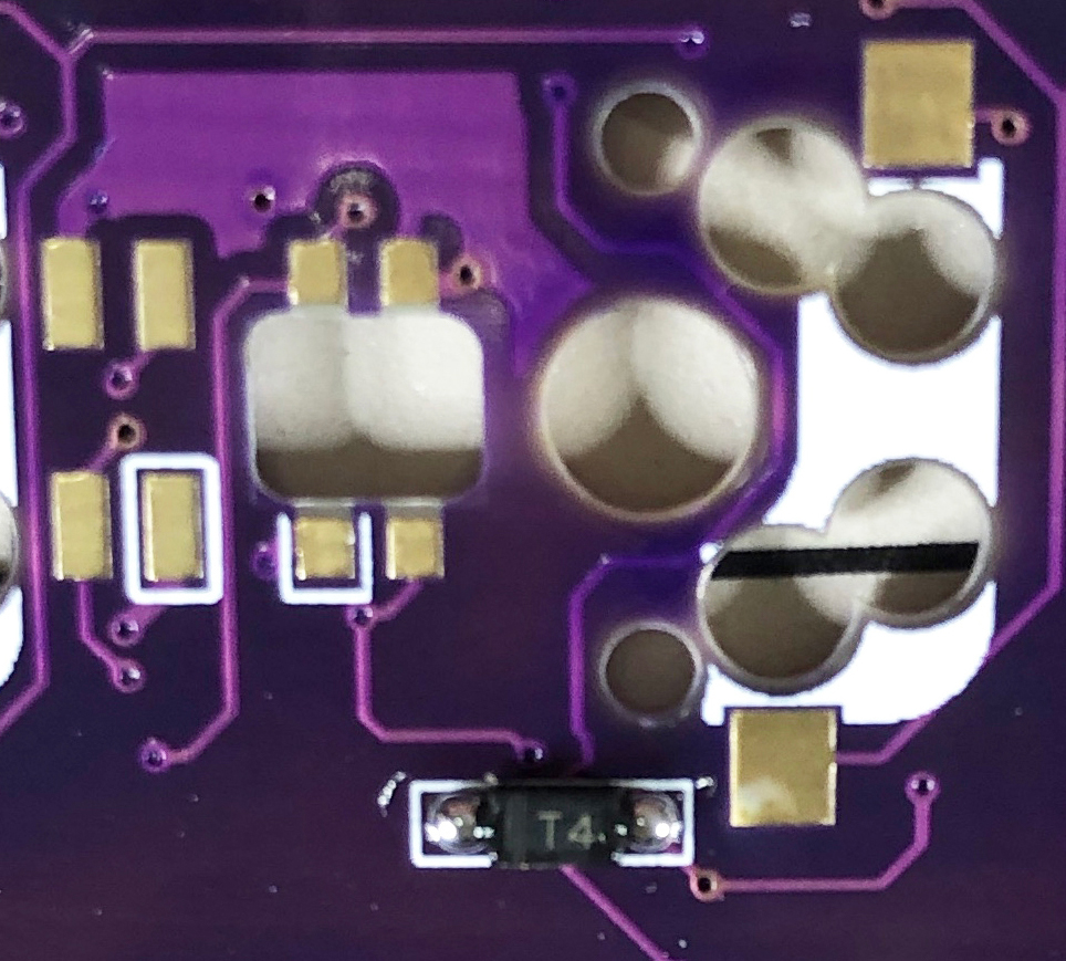
It is okay if the diode does not float when viewed from the side
|
|
when one foot is attached.
|
|
If it floats, press the diode with tweezers or your fingers
|
|
and reheat the soldered part with a soldering iron to clean it.
|
|
|
|
|
|
|
|
Then solder the other one.
|
|
Be careful not to apply too much,
|
|
as a small amount of solder is sufficient.
|
|
If you apply too much, you can remove it with a blotting wire
|
|
or by scooping it with a soldering iron.
|
|
|
|
If the amount of solder on the preliminary solder side is small,
|
|
additional soldering is performed, and if it is a mountain,
|
|
apply flux from above and heat it to clean it.
|
|
|
|
|
|
|
|
</details>
|
|
|
|
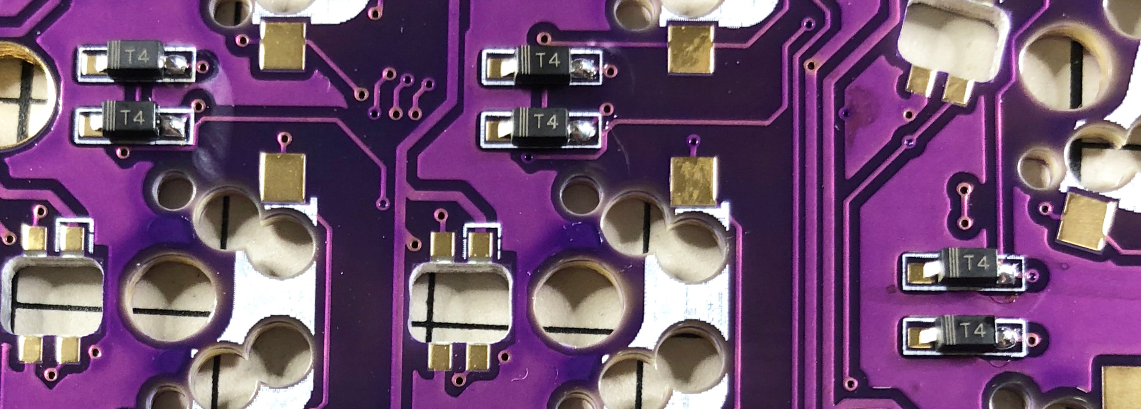
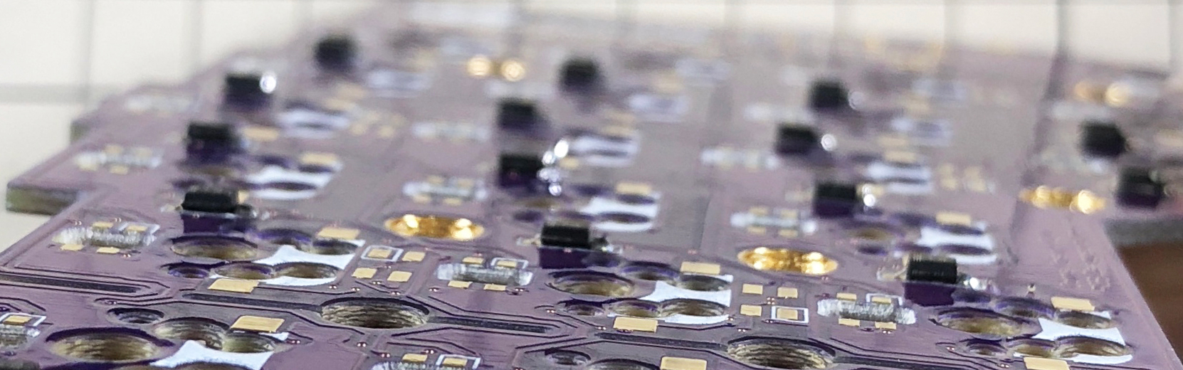
The diode is completed by soldering 42 pieces in total on the left and right.
|
|
|
|

|
|
|
|
### TRRS jack, reset switch, pin socket for OLED
|
|
|
|
Solder the TRRS jack, reset switch (tact switch),
|
|
and OLED pin socket as shown in the picture below.
|
|
|
|

|
|
|
|
Since it is a part that easily slips off,
|
|
you can solder it while holding the part by hand,
|
|
or fix it with masking tape and then solder it.
|
|
|
|
### ProMicro
|
|
|
|
Solder ProMicro in the following orientation
|
|
|
|

|
|
|
|
If you use spring-loaded pin headers (e.g. Conthrough),
|
|
you do not need to solder the back side.
|
|
Please refer to the [Helix Build Guide](
|
|
https://github.com/MakotoKurauchi/helix/blob/master/Doc/buildguide_en.md#pro-micro)
|
|
for details on how to use spring-loaded pin headers.
|
|
|
|

|
|
|
|
### OLED module
|
|
|
|
Insert the pin header into the pin socket for OLED first,
|
|
and then solder the pin header and OLED module.
|
|
At this time, the OLED module is easy to float,
|
|
so be careful not to float it while pressing it with your finger.
|
|
|
|

|
|
|
|
### Firmware
|
|
|
|
Write the firmware to ProMicro by referring to the following. \
|
|
<https://github.com/foostan/crkbd/blob/master/doc/firmware_en.md>
|
|
|
|
### Operation check
|
|
|
|
We recommend that you check the operation when the ProMicro and OLED module are attached.
|
|
If you do it at the very end, it will be difficult to isolate the problem.
|
|
|
|
To check the operation,
|
|
connect the left hand side to the PC with MicroUSB,
|
|
and connect the left hand side and the right hand side with the TRRS cable.
|
|
Since there may be defects such as jacks,
|
|
be sure to connect the left and right instead of one by one
|
|
before checking the operation.
|
|
If it is done correctly so far,
|
|
if you short the pad to attach the PCB socket with tweezers etc.,
|
|
the key pressed on the OLED module will be displayed.
|
|
|
|
### Top plate, switch
|
|
|
|
After attaching the key switch to the top plate, solder the key switch.
|
|
If you attach all the key switches to the top plate first,
|
|
it will be more difficult to attach the switches to the board,
|
|
so it is easier to attach only the end key switches first.
|
|

|
|
|
|
### OLED protective plate
|
|
|
|
Attach the OLED protective plate with M2 9mm spacers and M2 screws.
|
|
|
|

|
|

|
|
|
|
Especially for the screws on the back side,
|
|
tighten them firmly to attach the bottom foam after this.
|
|
|
|
### Bottom form
|
|
|
|
Finally, paste the bottom form.
|
|
This foam has an adhesive surface on one side
|
|
and a non-slip surface on the other side.
|
|
Stick the adhesive side firmly to the PCB.
|
|
|
|

|
|
|
|
That's it.
|
|
|
|

|