11 KiB
Build Guide
This is the build guide for Corne Chocolate. Click here for the Corne Cherry build guide.
Parts
Required
| Name | Count | Remarks |
|---|---|---|
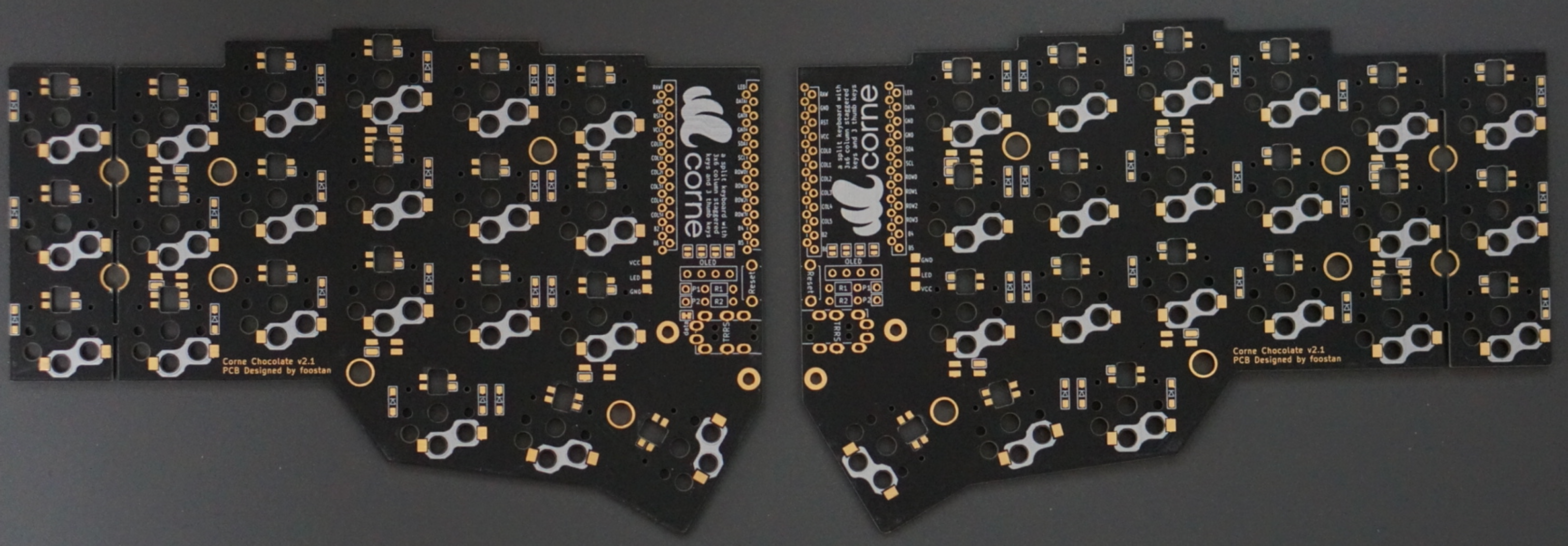
| PCB | 2 pieces | |
| Top plate | 2 pieces | |
| Bottom plate | Two pieces | PCB type and acrylic type are available |
| Pro Micro protection plate | 2 pieces | |
| Pro Micro | 2 | |
| TRRS Jack | 2 | |
| Tactile switch | 2 pieces | |
| Diode | 42 pieces | Compatible with chip components only |
| Kailh PCB Socket (for Choc) | 42 | |
| Key switch | 42 pieces | Compatible with Choc (low profile) only |
| Key-caps | 42 | 1u 40, 1.5u 2 |
| OLED module | 2 pieces | |
| 4 pin headers | 2 | |
| 4 pin sockets | 2 | |
| Spacer M2 4.5mm | 10 | |
| Spacer M2 9mm | Four | |
| Screw M2 4mm | 28 | |
| Cushion rubber | 8 pieces | |
| TRS (3 pole) cable | 1 | TRRS (4 pole) cable also available |
| Micro USB Cable | 1 |
Optional
| Name | Count | Remarks |
|---|---|---|
| SK6812MINI | 54 | 42 for backlight, 12 for under-glow |
Advance preparation
If you build the firmware yourself,
it will take some time to set up the environment,
so it's best to start at the beginning.
For more information,
please see https://github.com/foostan/crkbd/blob/master/doc/firmware_en.md.
Building
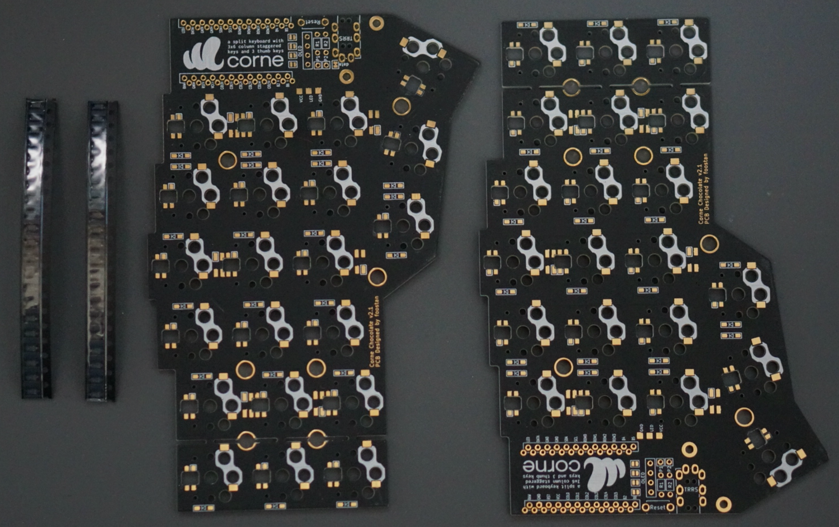
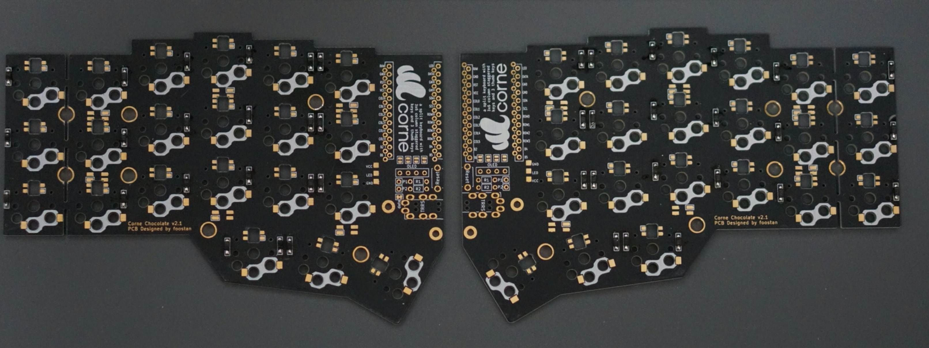
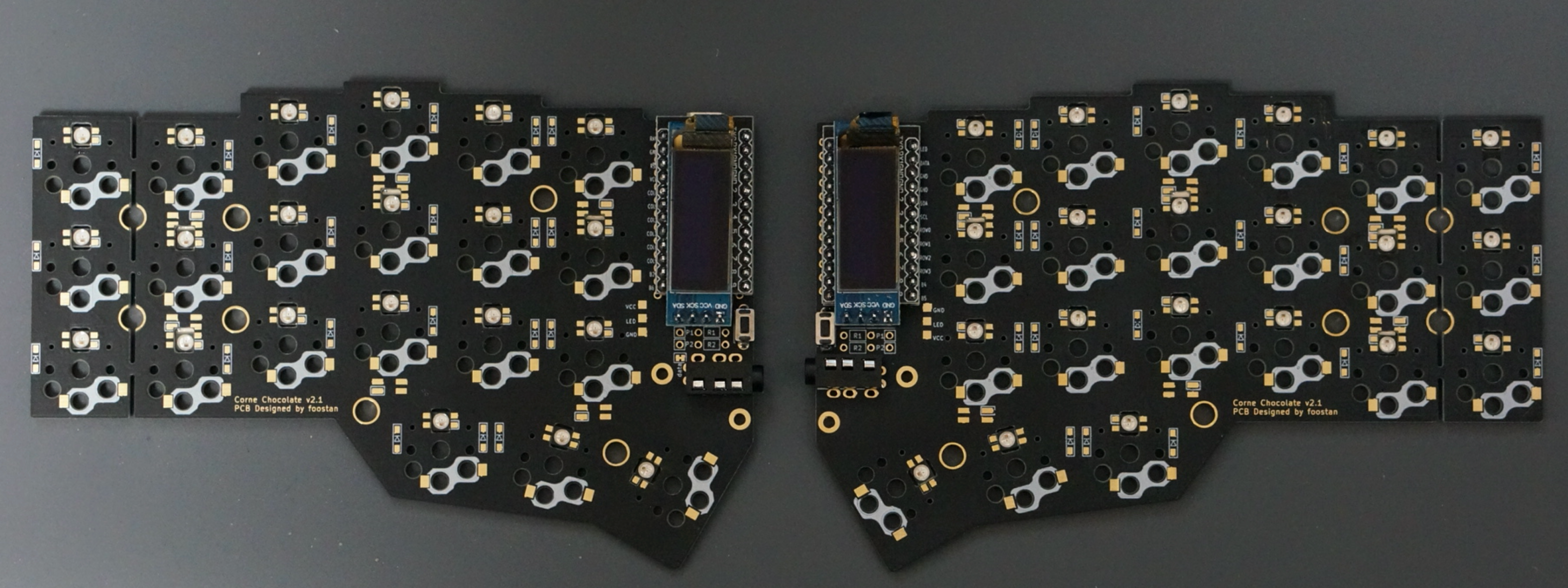
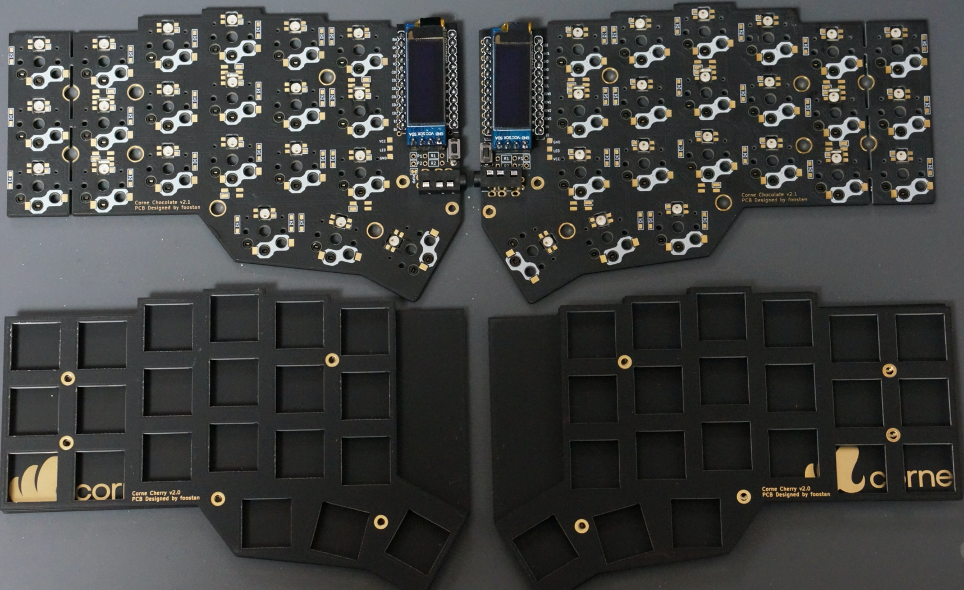
Since the PCB is reversible, you first have to decide which one to use for the left side.
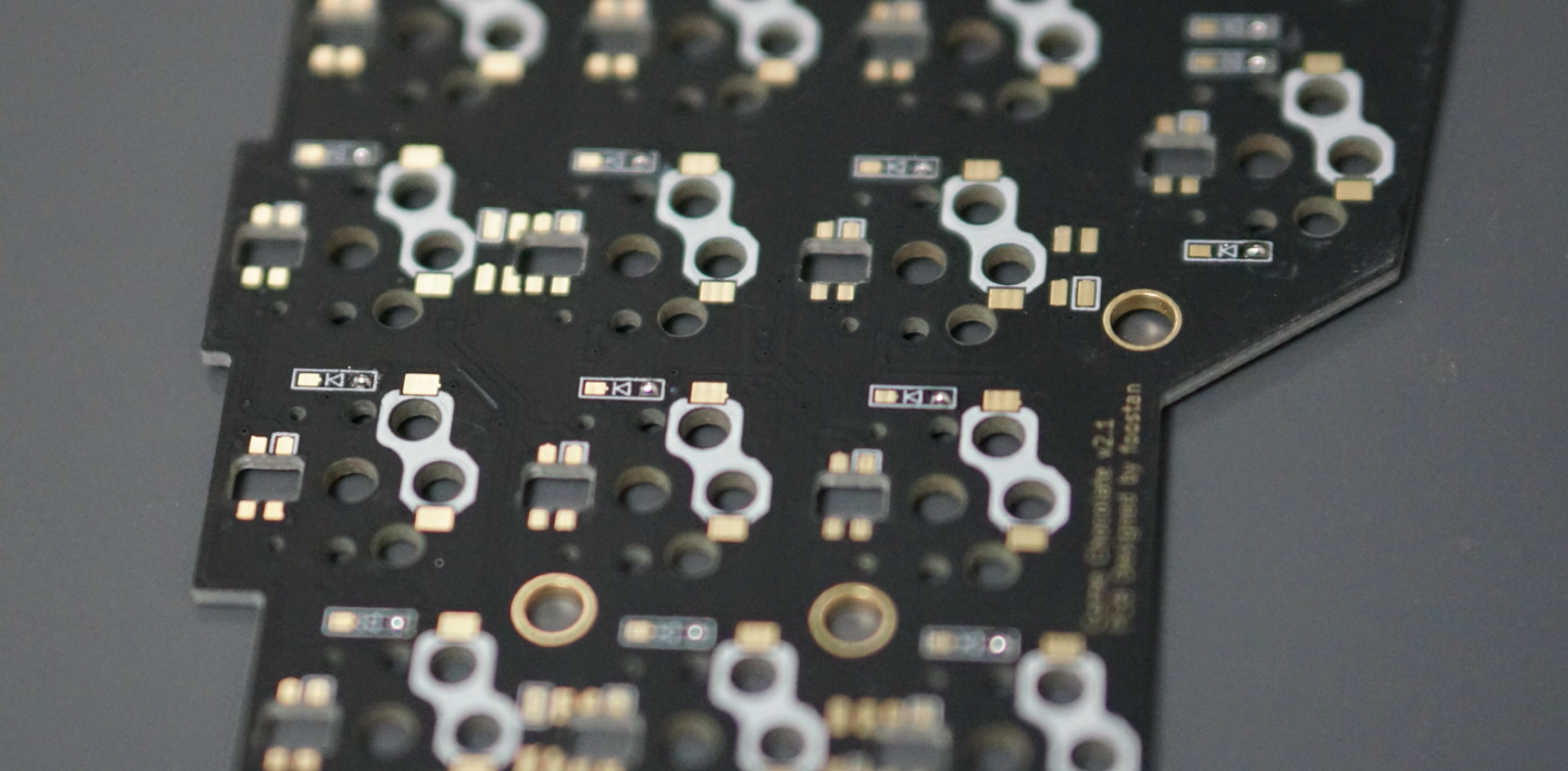
Diodes
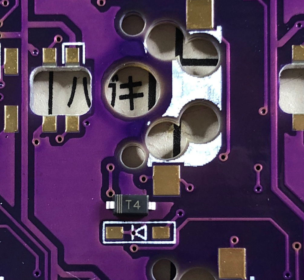
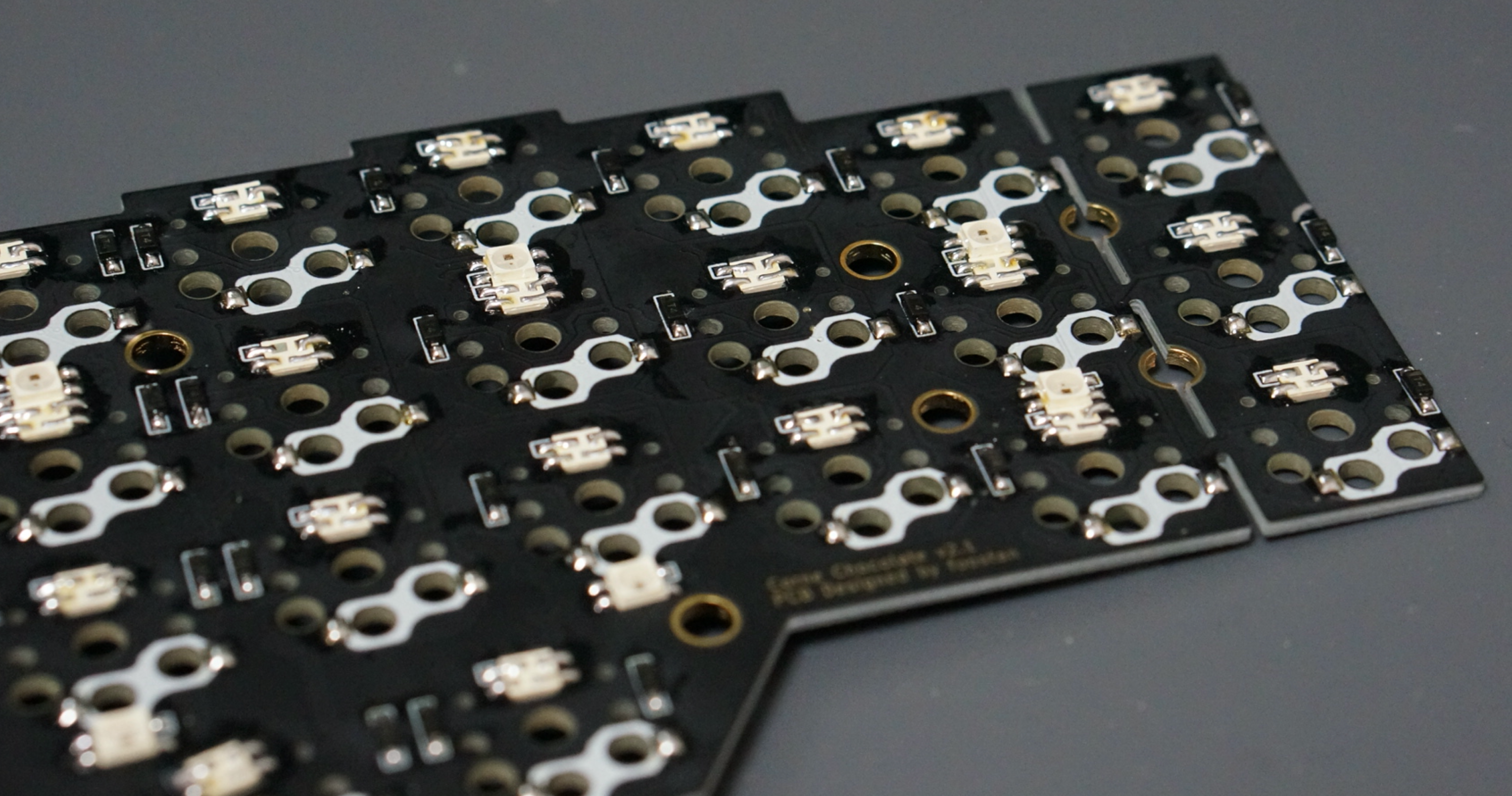
Solder the diodes to the PCB.
On Corne Cherry, it is up to you to choose which side to attach, but with Corne Chocolate you must be sure to attach it to the back. Mounting on the front will interfere with the top plate.
Since the diodes are very small, it is easier to work with tweezers and inverted tweezers. Since the mounting orientation of the diode is crucial, it is possible to proceed smoothly if you arrange the columns and rows to be mounted in advance, as shown in the following photo.
The orientation of the diode is as follows. Attach the chip component so that the "|||" mark on the diode is facing the "|" of the diode mark "|◁" on the PCB (image from Corne Cherry).
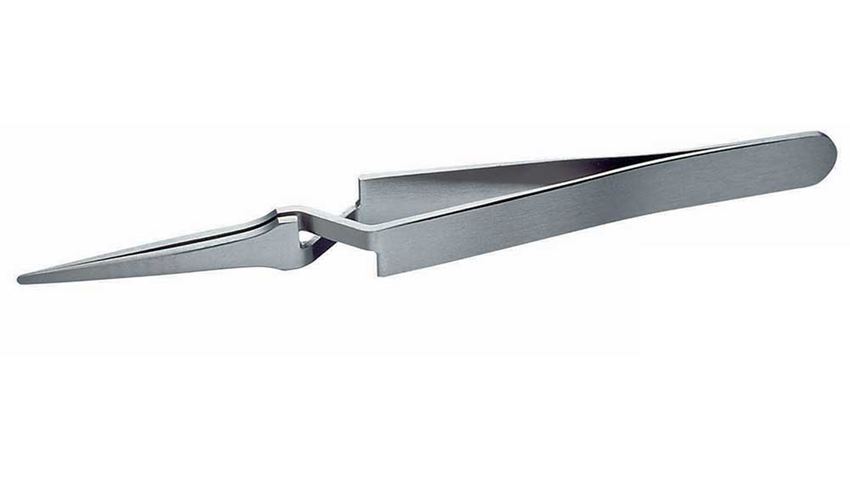
Tip for soldering on SMD parts: First put solder only on the right side of the pad.
Next, solder one of the diodes by melting the solder you already put on the board. At this time, it is recommended to use reverse-action tweezers, so that you can hold the SMD part firmly without applying force, and concentrate on alignment and soldering instead. Also, if the soldering iron is too hot or the solder is touched too long, the flux contained in the solder may evaporate and form an undesirable pile solder, but since it can be repaired later, so at this point you should only care about attaching parts. It's okay.
Then solder the other pin. Be careful not to apply too much solder, as a small amount is sufficient. If you have applied too much, you can remove it with a suction pump, blotting wire or by scooping it with a soldering iron.
If the amount of solder on the pre-soldering side is too small, add more soldering, and if it is pilled up, apply flux from above and heat to clean.
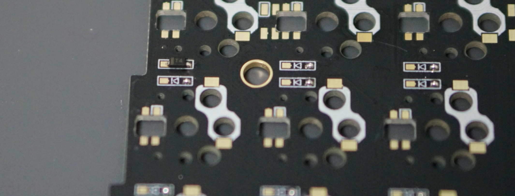
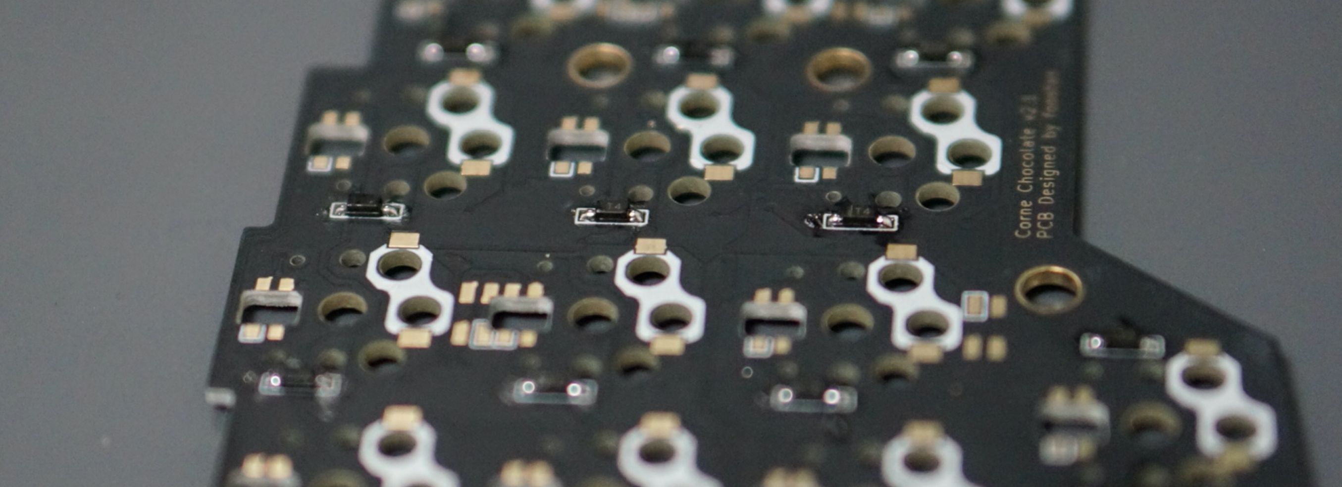
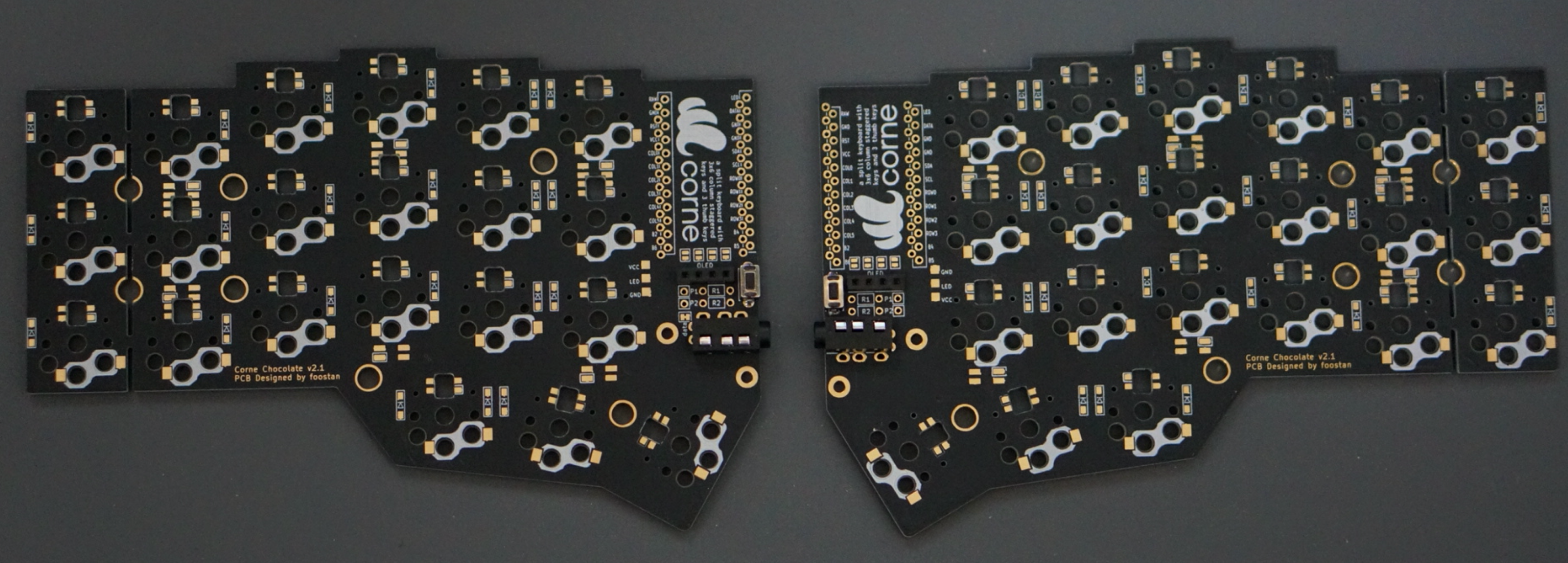
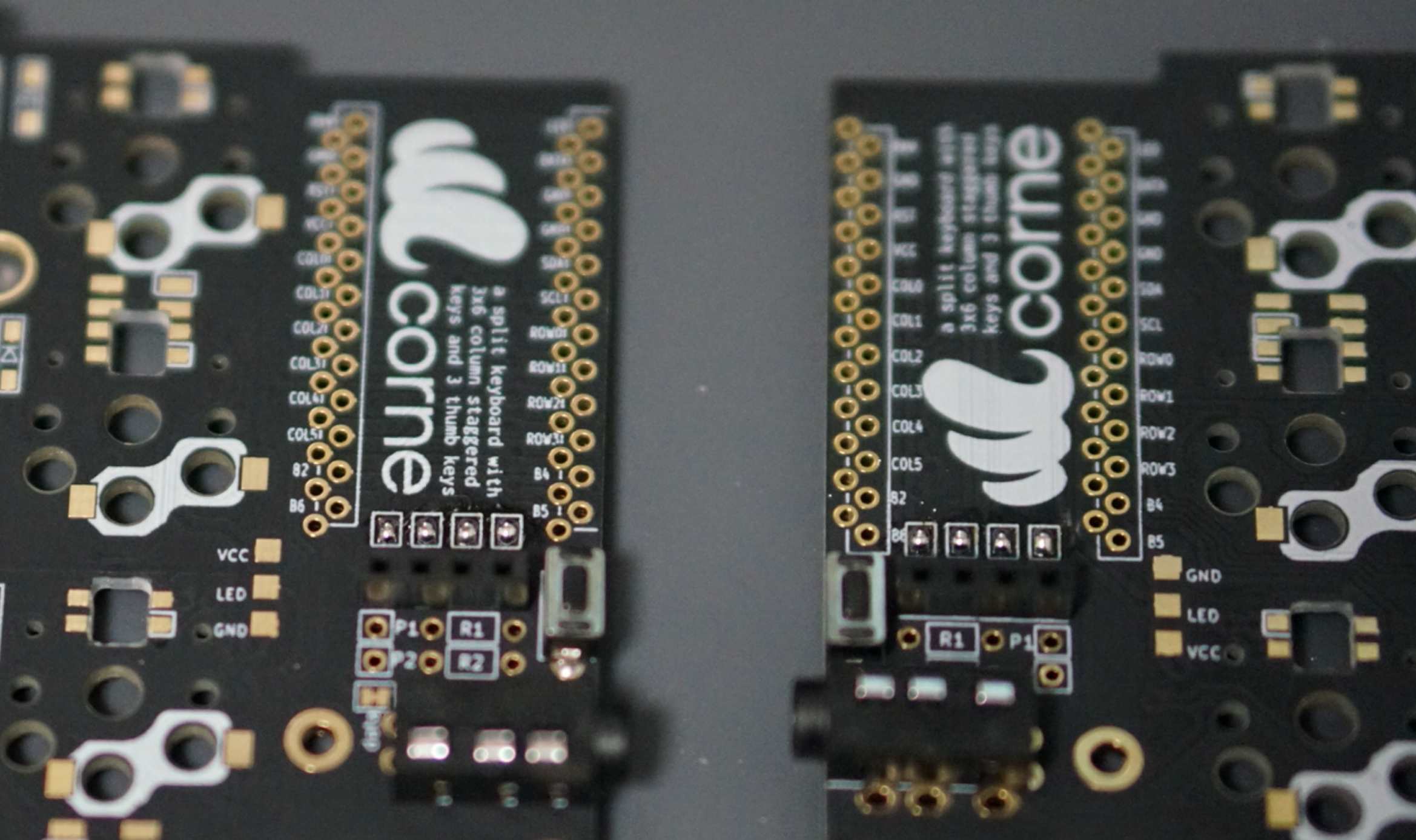
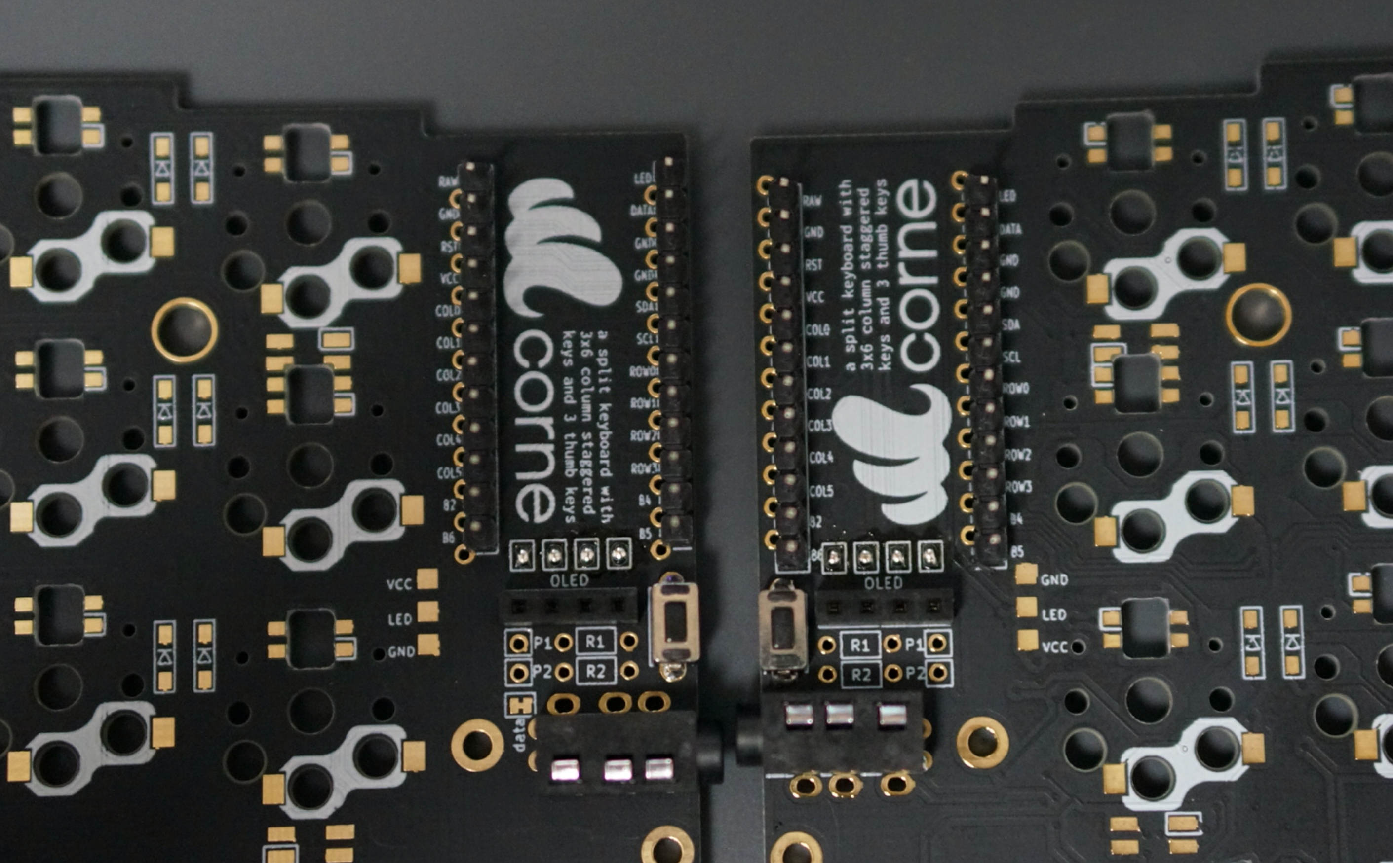
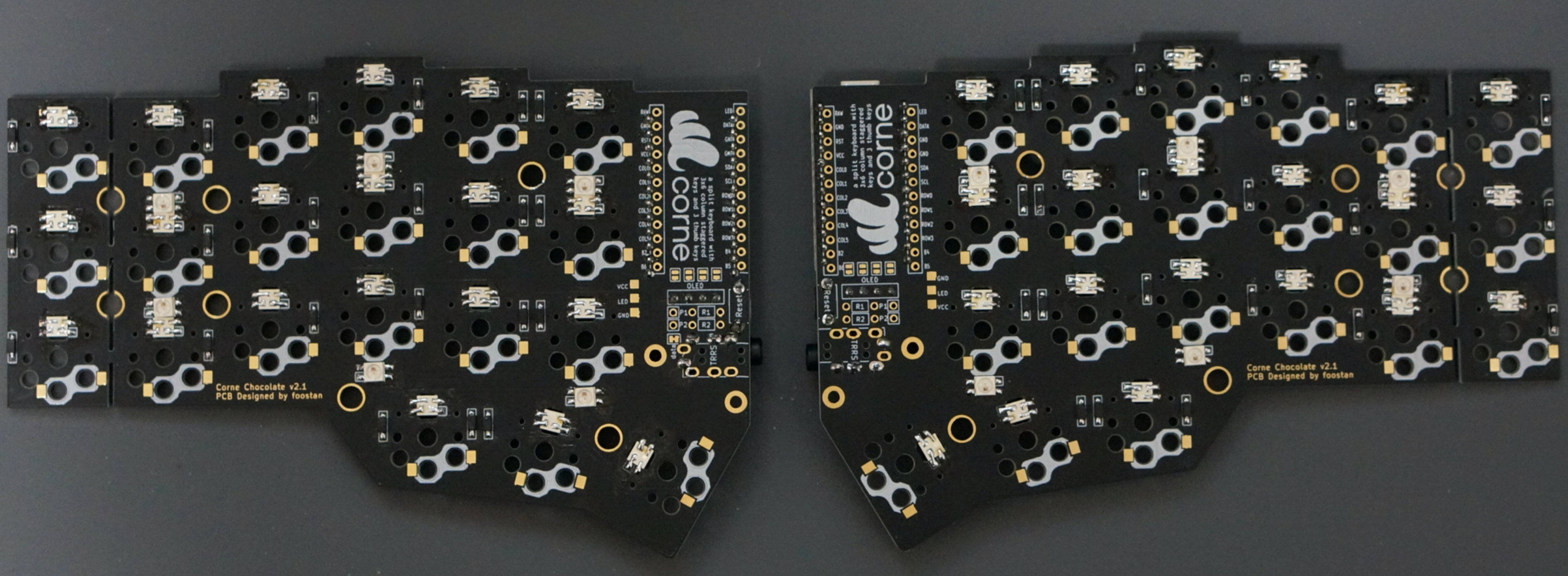
TRRS jack, reset switch, pin socket
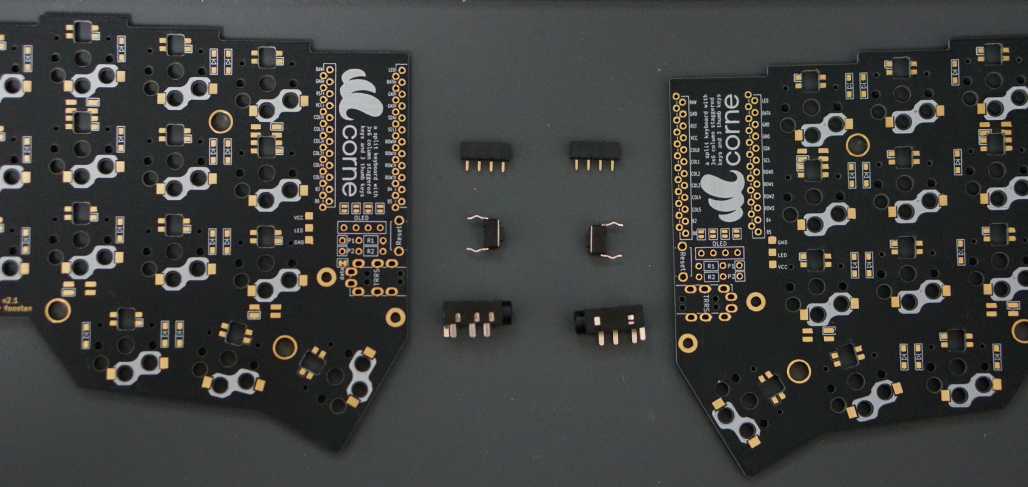
Solder the TRRS jack, reset switch and pin socket to the front of the PCB as shown in the picture below. Since the diode is attached on the back side, it will be on the opposite side.
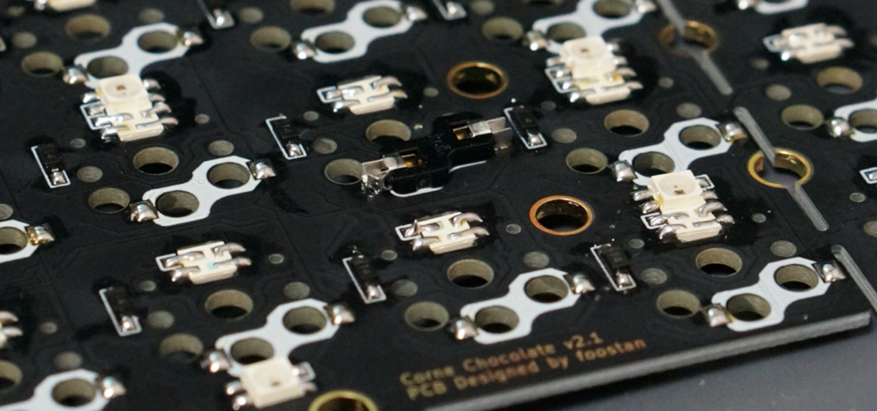
Jumpers for OLED modules
When using an OLED module, use solder as jumpers (4 times per side) as follows. Please jumper only on the surface.
If the jumper doesn't work, you probably have a small amount of solder, or the flux has vaporized. If so, you can fix the jumper by applying more solder or separate flux.
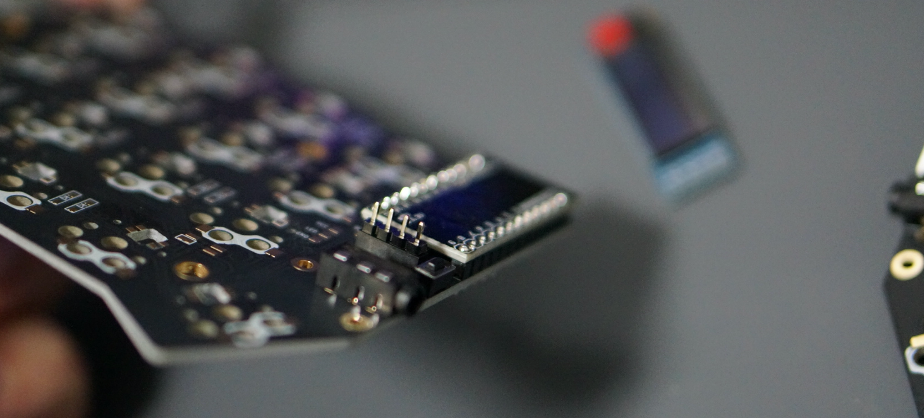
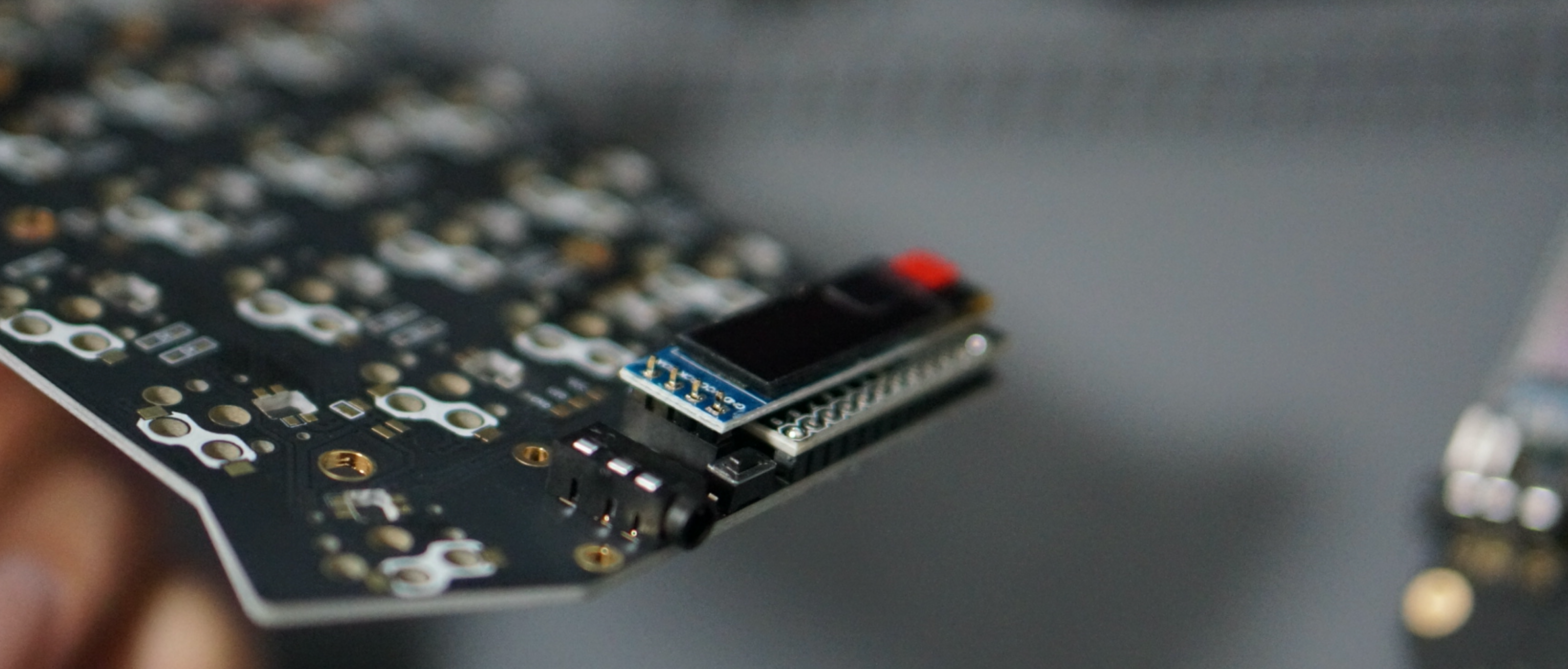
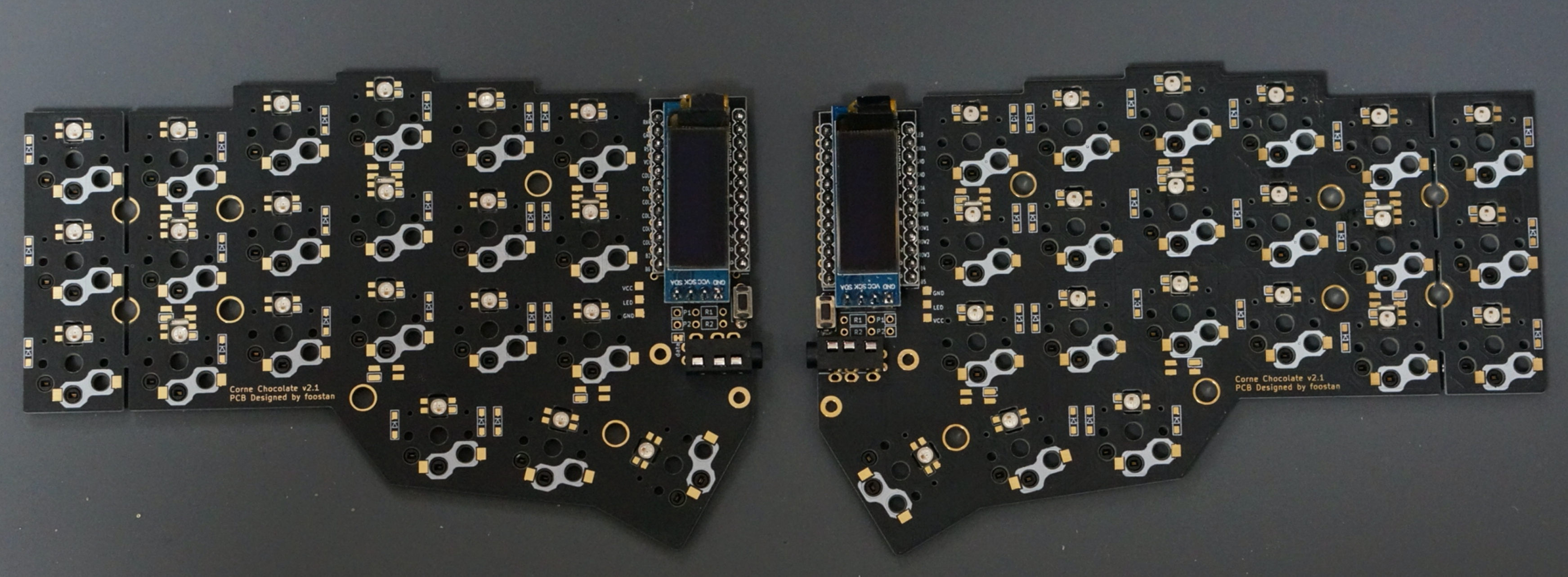
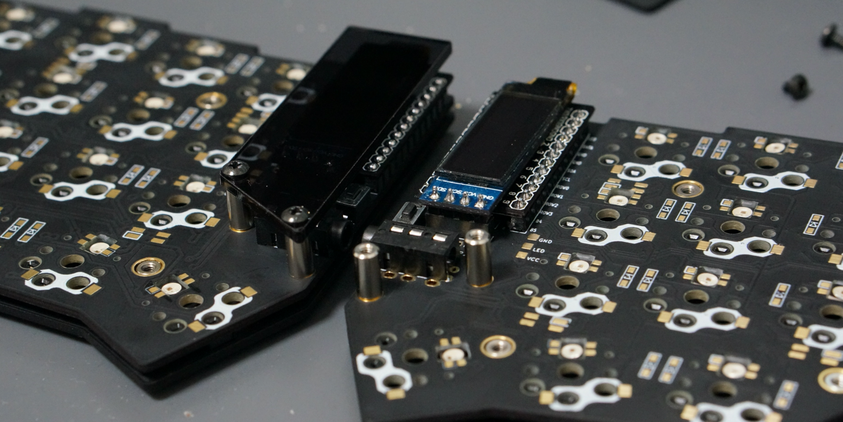
Pro Micro
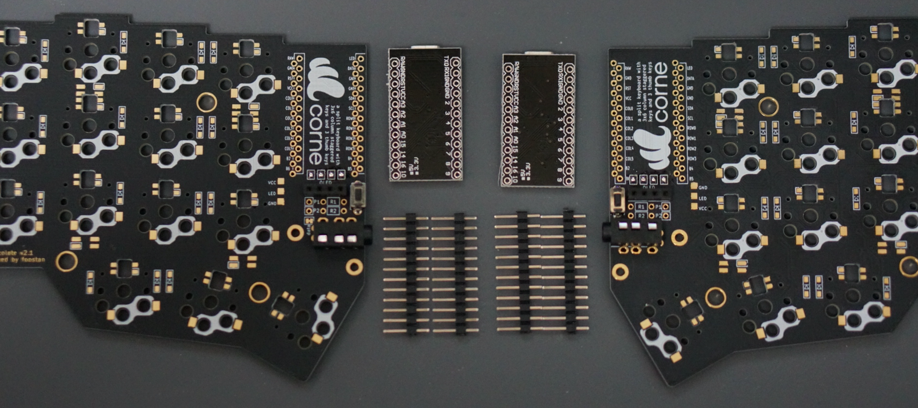
Solder the pin headers to the white frame and solder the Pro Micro with back side up.
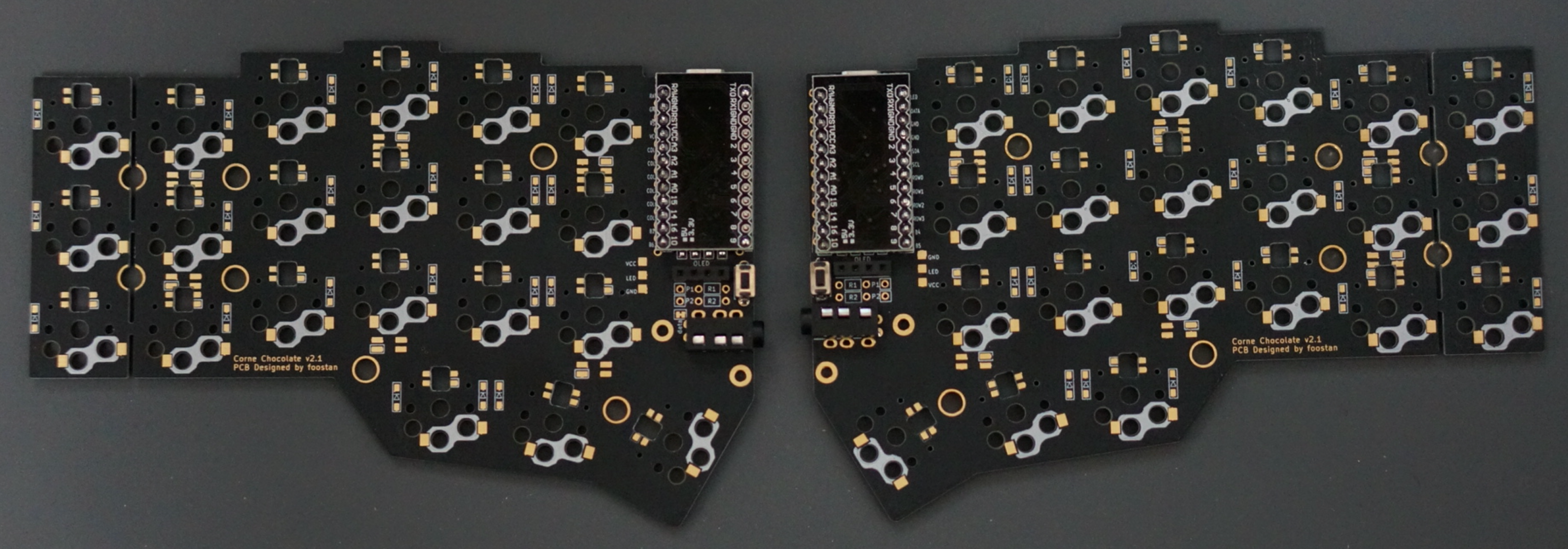
When using the spring-loaded pin headers, please refer to the Helix Build Guide.
OLED module
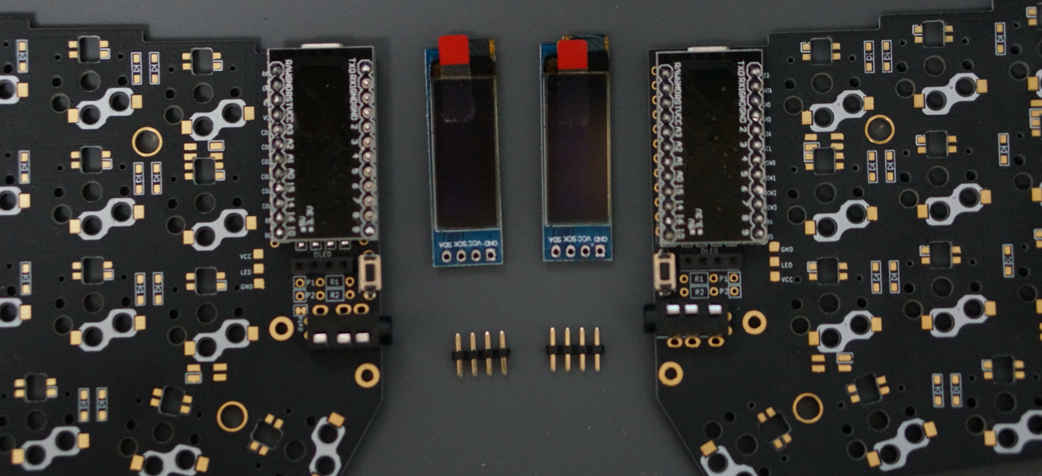
Insert the pin header into the OLED pin socket first, then solder the pin header and the OLED module. At this time, make sure that the OLED module sits tightly on the socket while holding it down with your finger, because it tends to stick out easily.
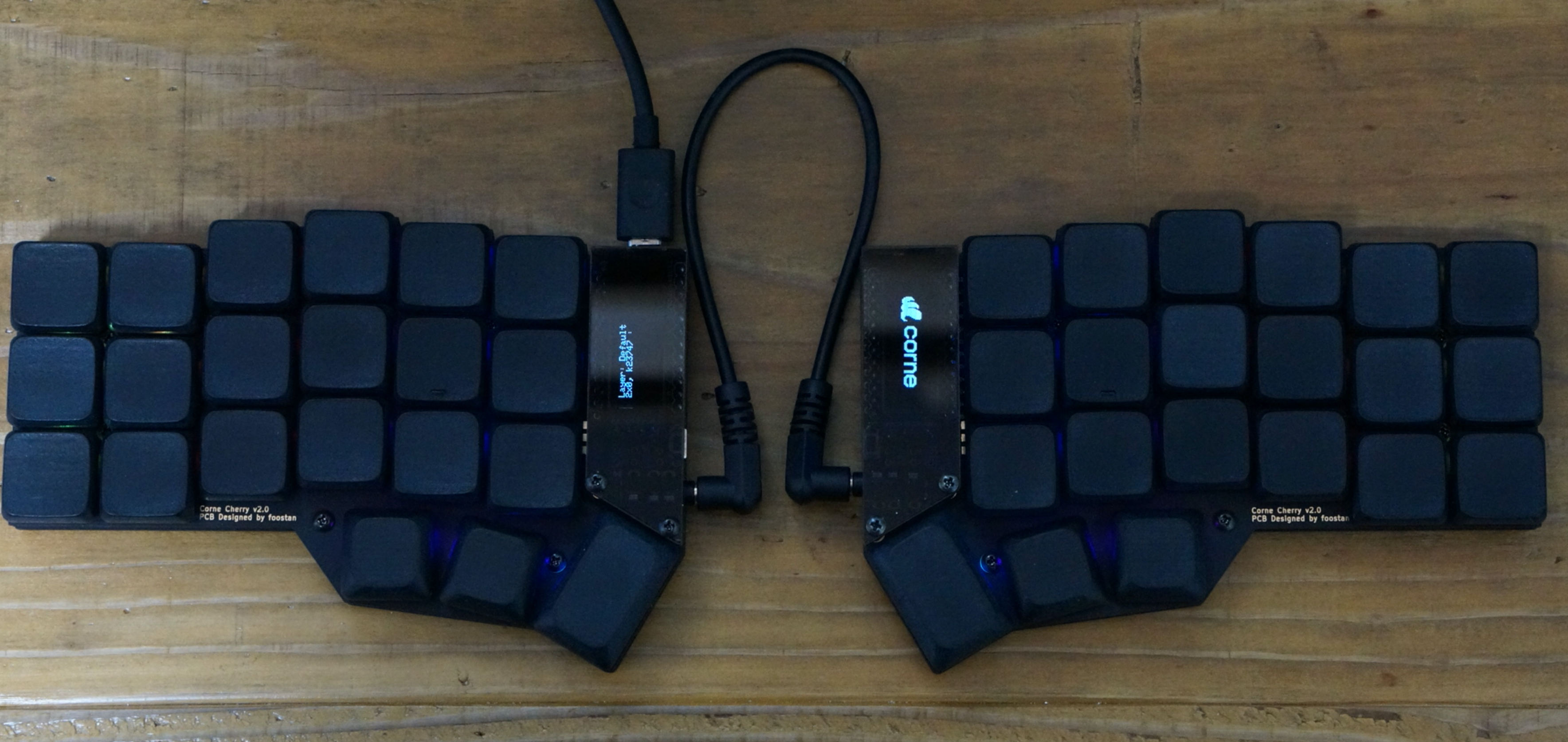
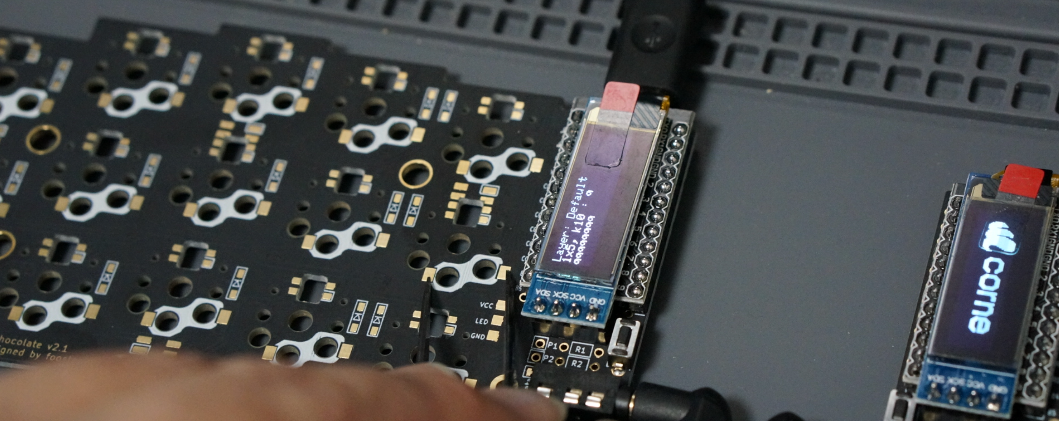
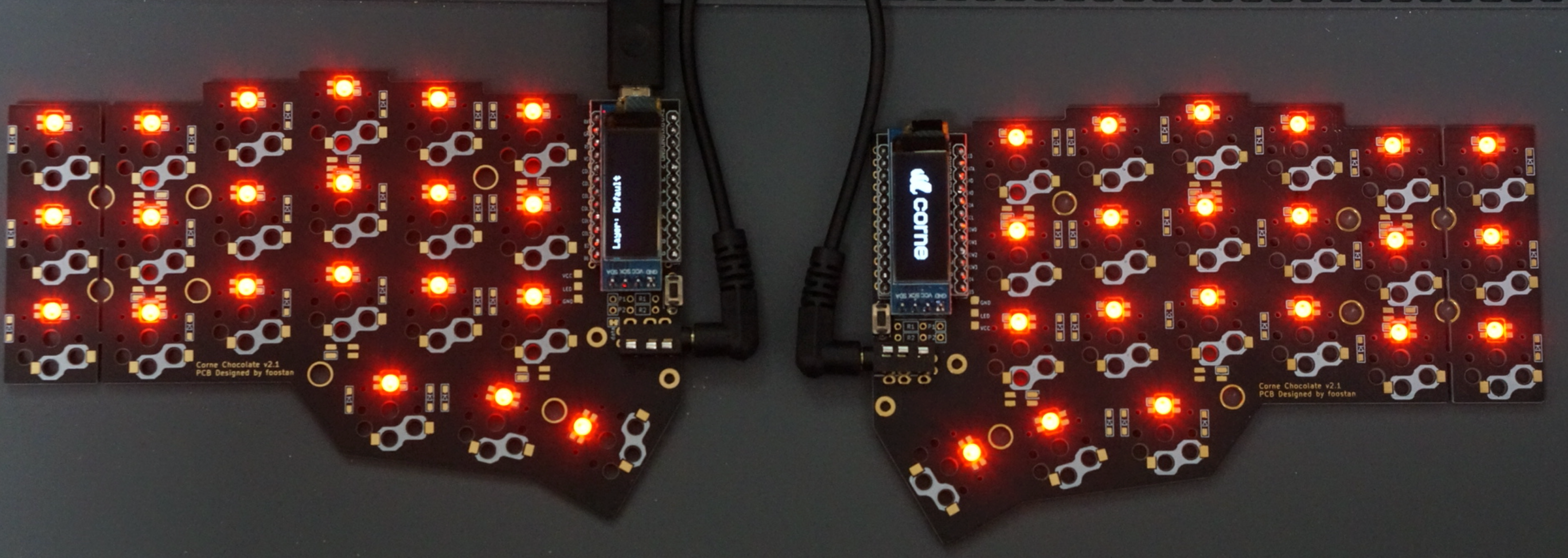
Operation check
We recommend that you check the operation at the stage where the Pro Micro and OLED modules are attached (it is difficult to isolate the problem at the end).
Before checking the correct operation, flash the crkbd firmware to the Pro Micro by referring to the Firmware section below (be sure to insert it on both sides).
Operation confirmation is performed by connecting the left hand side to a PC with Micro USB and connecting the left hand side and the right hand side with a TRS cable. Since there may be a defect such as a jack, make sure to connect the left and right instead of one by one before checking the operation. If you have done this correctly, short-circuit the pad to attach the PCB socket with tweezers, and the key pressed on the OLED module will be displayed.
LED (optional)
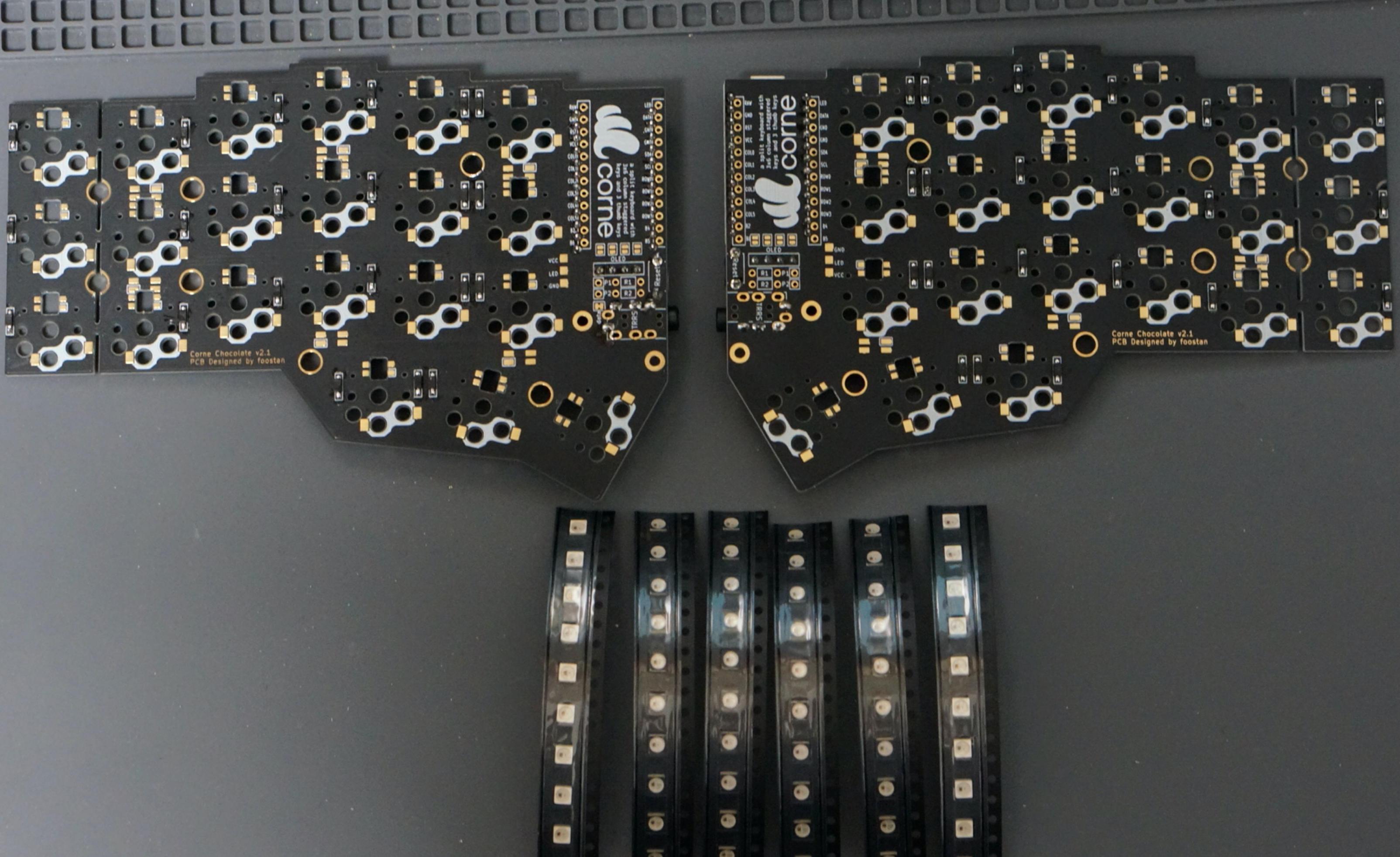
I will install SK6812MINI. The LED can be mounted even after completion, so if you are worried about mounting it, we recommend that you skip this chapter and complete it first.
SK6812MINI is very heat sensitive and breaks easily. We recommend using a soldering iron with a temperature control function and operating at a temperature of about 220°C to 270°C. Even if the temperature is set that low, the LED will be damaged if the iron is left on it for a long time, so try to solder as quickly as possible. Solder four LEDs at a time, but we recommend soldering two at a time instead of four at a time to prevent the LED temperature from rising, as this will make it less likely to overheat.
First, check the mounting position.
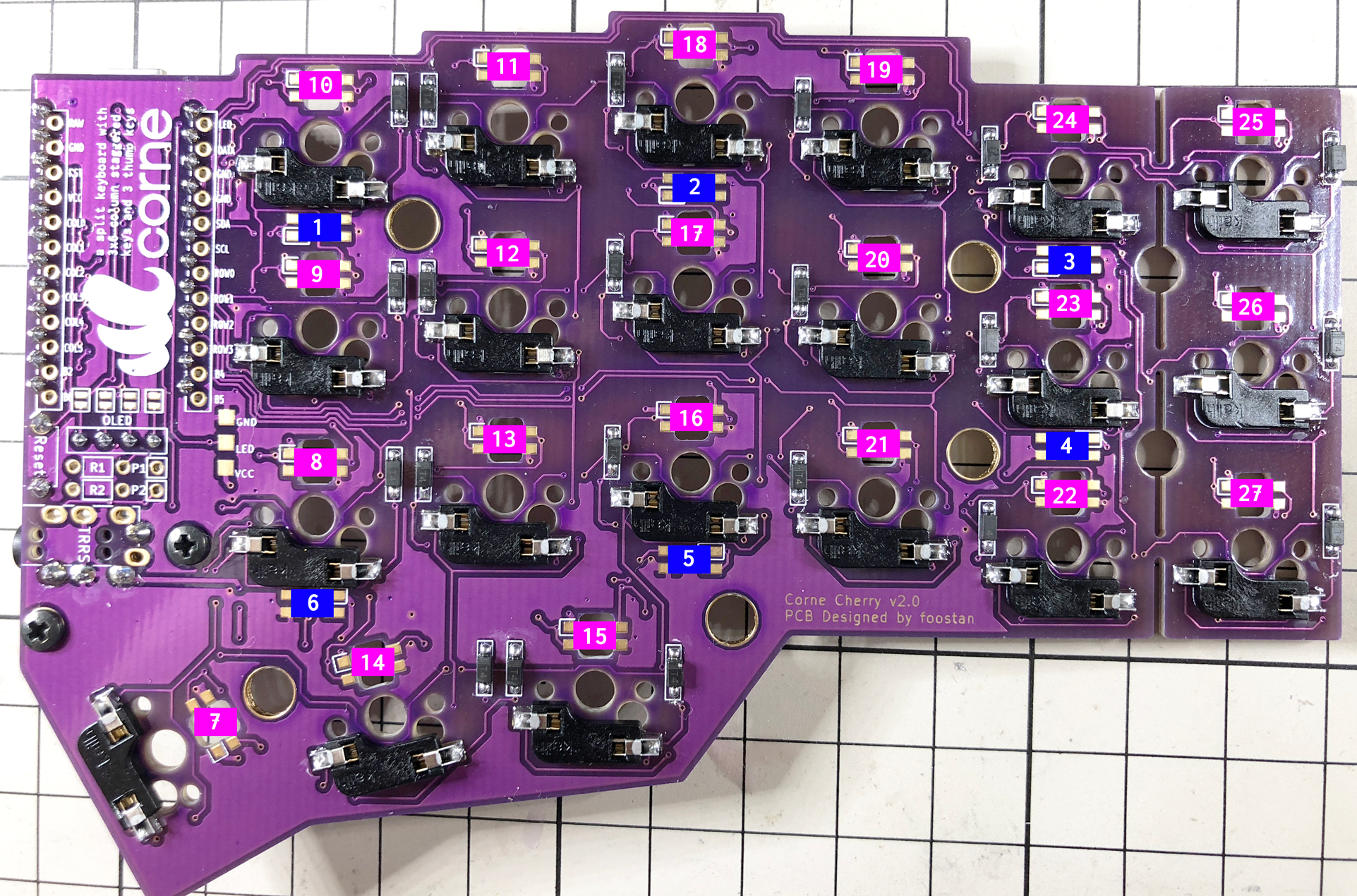
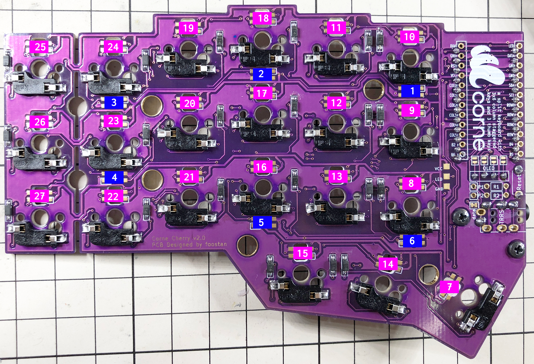
Solder 1 - 6 so that the back side (under-glow) shines, 7 - 27 so that the front side (back-light) shines. Below is the location to attach the LED (image from Corne Cherry).
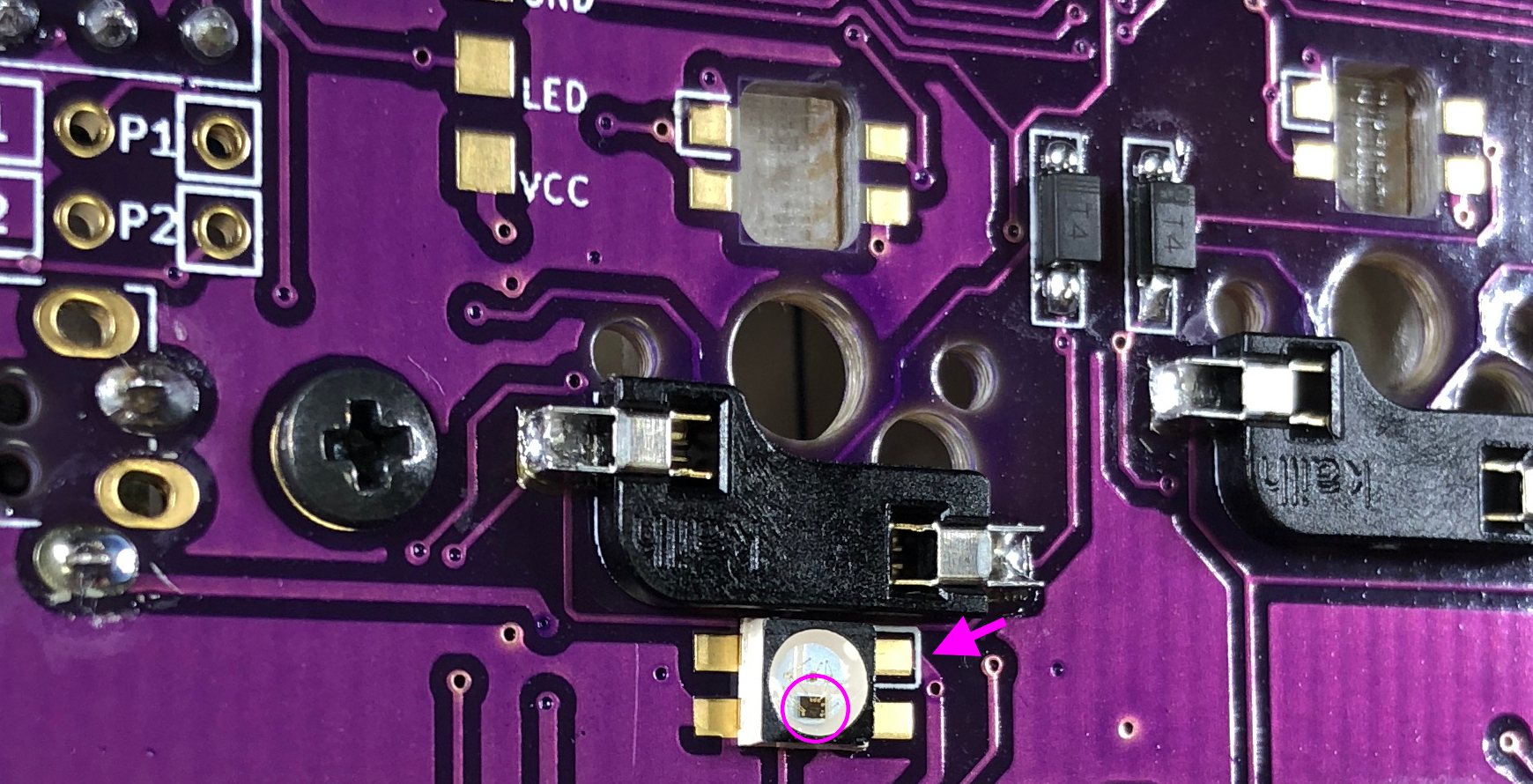
For LEDs 1 to 6, solder the part so that the black part circled below is on the bottom and the silk mark indicated by the arrow is on the top. Note that the direction changes between 1 - 3 and 4 - 5.
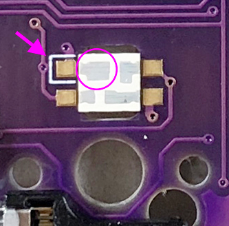
For 7 - 27, perform soldering so that the largest pad surrounded by a circle and the silk mark indicated by an arrow are adjacent to each other, as shown below.
If everything was successfully soldered, it will glow as follows. If the LED lights only halfway, the LEDs are connected in the order of the numbers. Therefore, it is likely that the LED that does not emit light or the previous LED are incorrectly soldered or damaged.
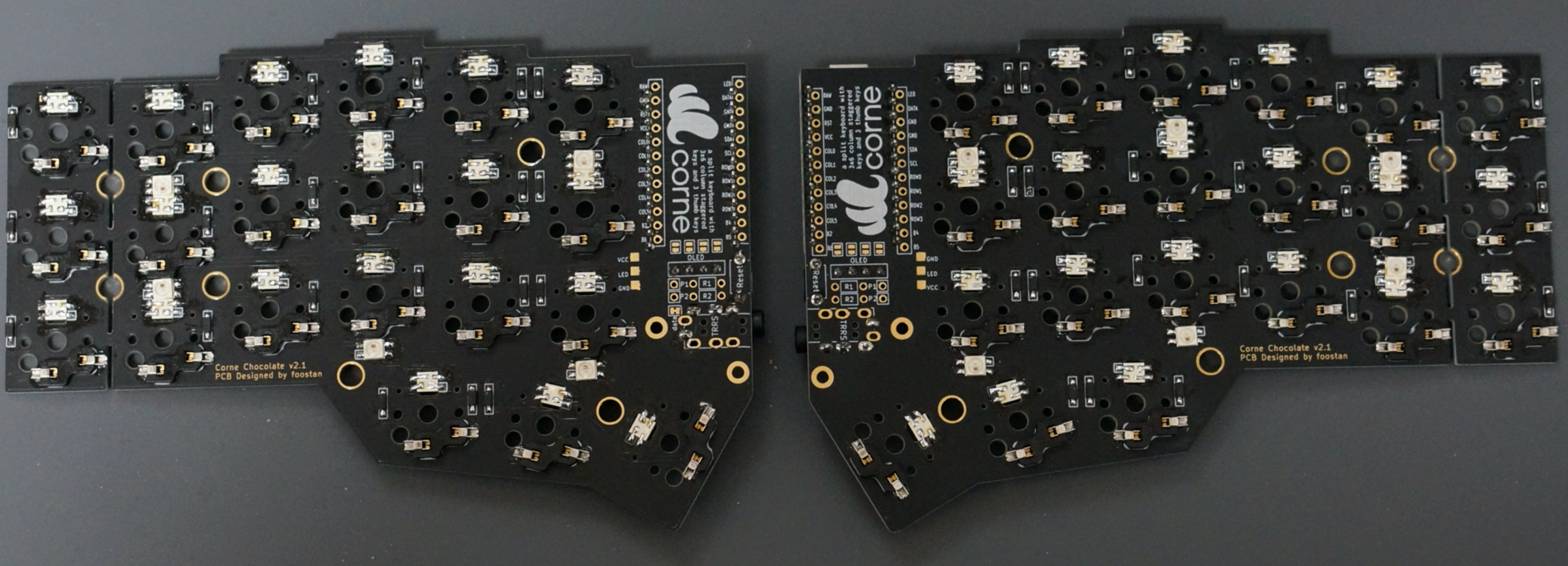
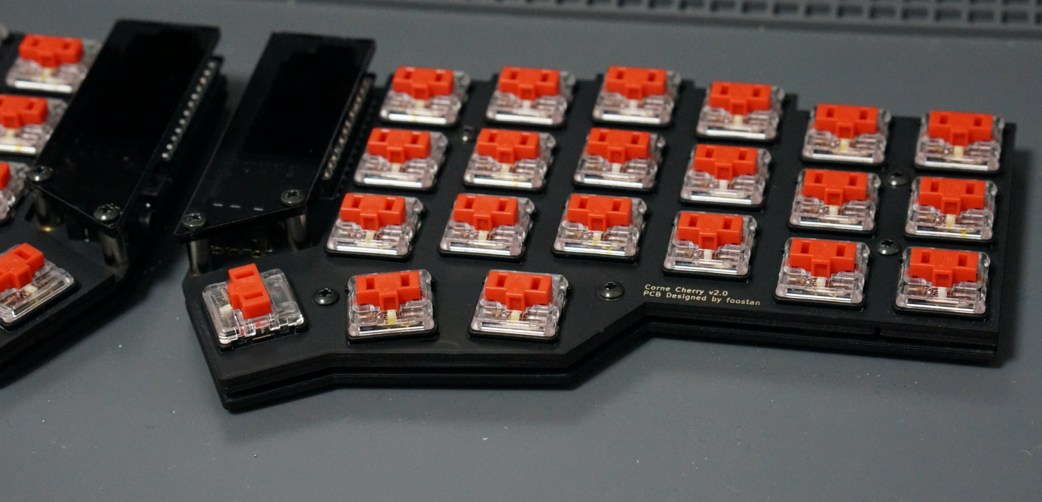
Kailh PCB Socket
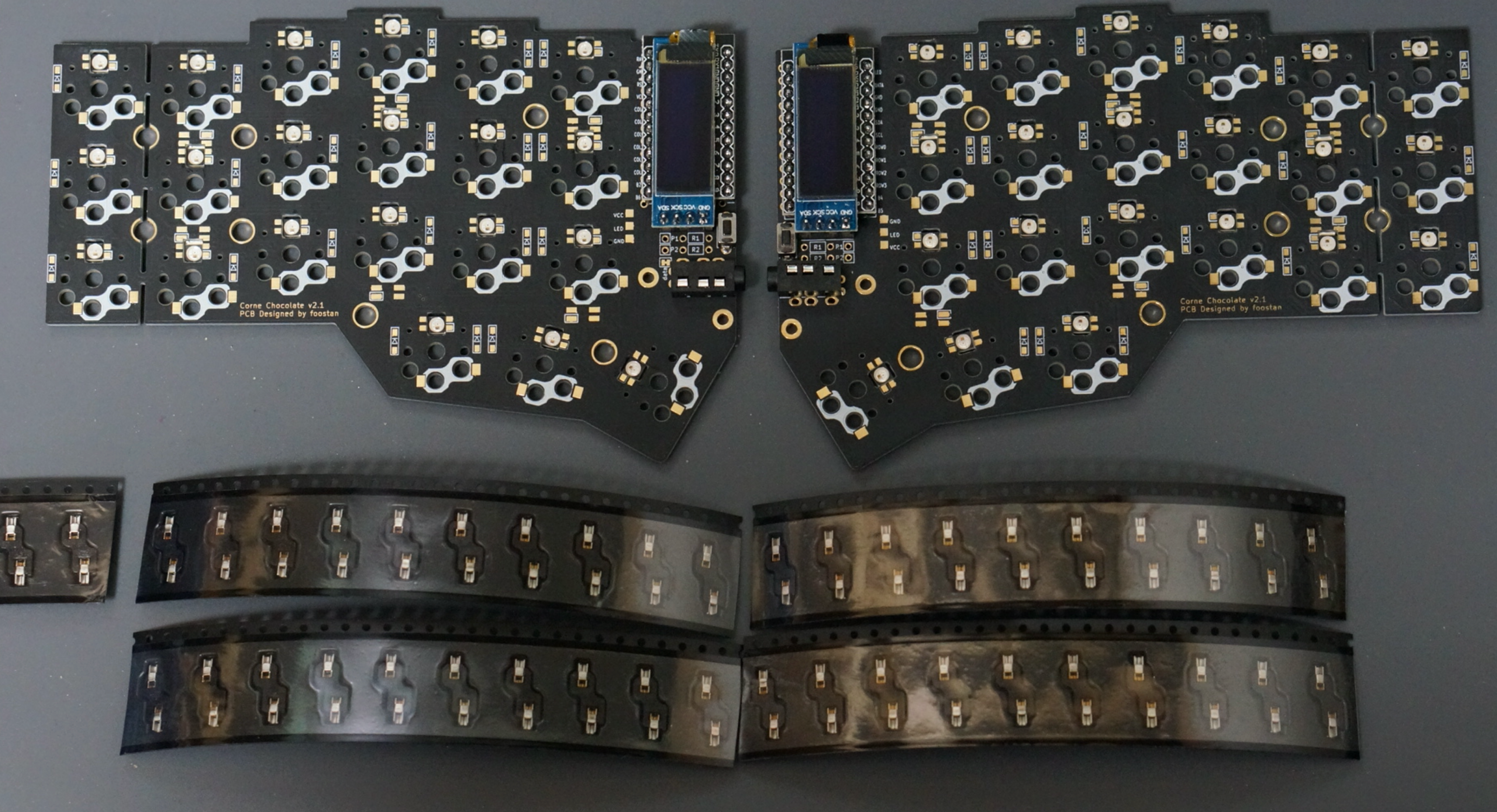
Apply solder to the pads on both sides on the back. It is difficult to add it later, so please fill it up beforehand.
Insert the socket and melt the solder. At this time, hold the socket with tweezers or your fingers so that the socket sticks to the board.
The soldering is now complete.
Plate, switch
Use 4.5mm spacers for the top and bottom plates and 9mm spacers for the OLED.
In addition, it is recommended to paint the side of the plate with a black marker because it looks better.
Firmware
See below to flash the firmware to the ProMicro.
https://github.com/foostan/crkbd/blob/master/doc/firmware_en.md
This is the end.