mirror of https://github.com/foostan/crkbd.git
284 lines
11 KiB
Markdown
284 lines
11 KiB
Markdown
# Build Guide
|
|
|
|
This is the build guide for Corne Chocolate.
|
|
[Click here for the Corne Cherry build guide](
|
|
https://github.com/foostan/crkbd/blob/master/corne-cherry/doc/buildguide_en.md).
|
|
|
|
## Parts
|
|
|
|
### Required
|
|
|
|
| Name | Count | Remarks |
|
|
|:-|:-|:-|
|
|
| PCB | 2 pieces | |
|
|
| Top plate | 2 pieces | |
|
|
| Bottom plate | Two pieces | PCB type and acrylic type are available |
|
|
| Pro Micro protection plate | 2 pieces | |
|
|
| Pro Micro | 2 | |
|
|
| TRRS Jack | 2 | |
|
|
| Tactile switch | 2 pieces | |
|
|
| Diode | 42 pieces | Compatible with chip components only
|
|
| Kailh PCB Socket (for Choc) | 42 | |
|
|
| Key switch | 42 pieces | Compatible with Choc (low profile) only |
|
|
| Key-caps | 42 | 1u 40, 1.5u 2 |
|
|
| OLED module | 2 pieces | |
|
|
| 4 pin headers | 2 | |
|
|
| 4 pin sockets | 2 | |
|
|
| Spacer M2 4.5mm | 10 | |
|
|
| Spacer M2 9mm | Four | |
|
|
| Screw M2 4mm | 28 | |
|
|
| Cushion rubber | 8 pieces | |
|
|
| TRS (3 pole) cable | 1 | TRRS (4 pole) cable also available |
|
|
| Micro USB Cable | 1 | |
|
|
|
|
### Optional
|
|
|
|
| Name | Count | Remarks |
|
|
|:-|:-|:-|
|
|
| SK6812MINI | 54 | 42 for backlight, 12 for under-glow |
|
|
|
|
## Advance preparation
|
|
|
|
If you build the firmware yourself,
|
|
it will take some time to set up the environment,
|
|
so it's best to start at the beginning. \
|
|
For more information,
|
|
please see <https://github.com/foostan/crkbd/blob/master/doc/firmware_en.md>.
|
|
|
|
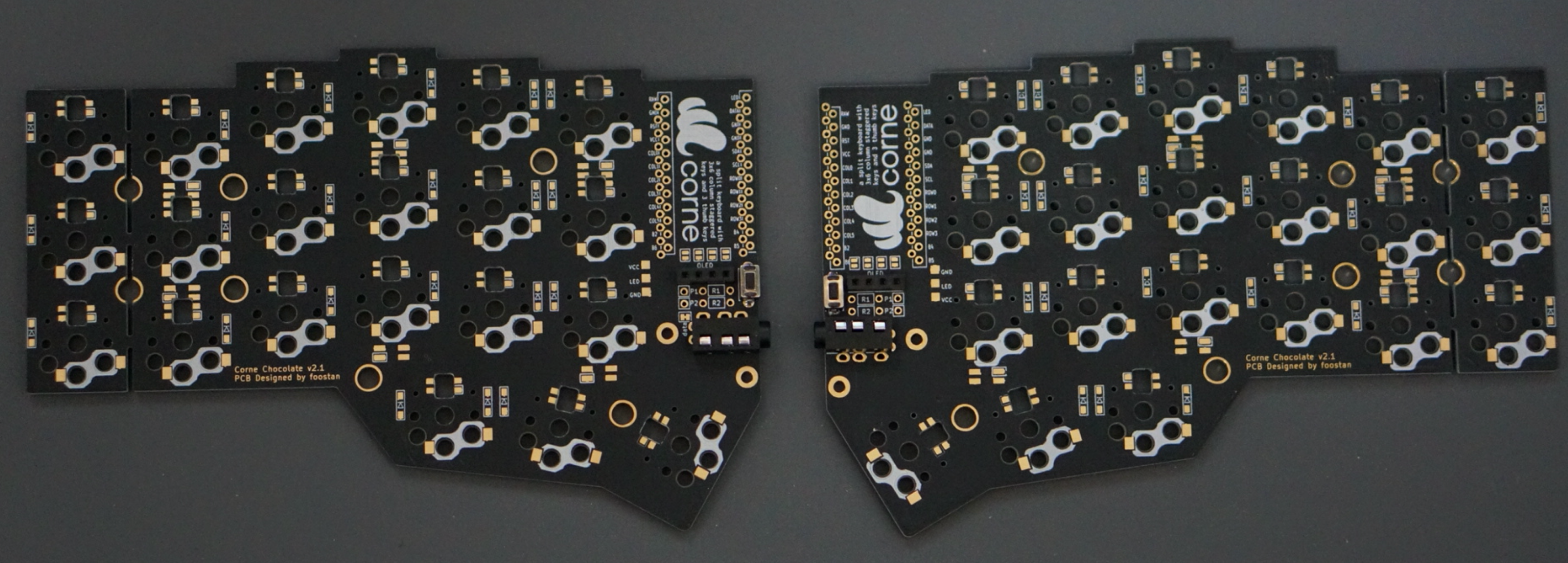
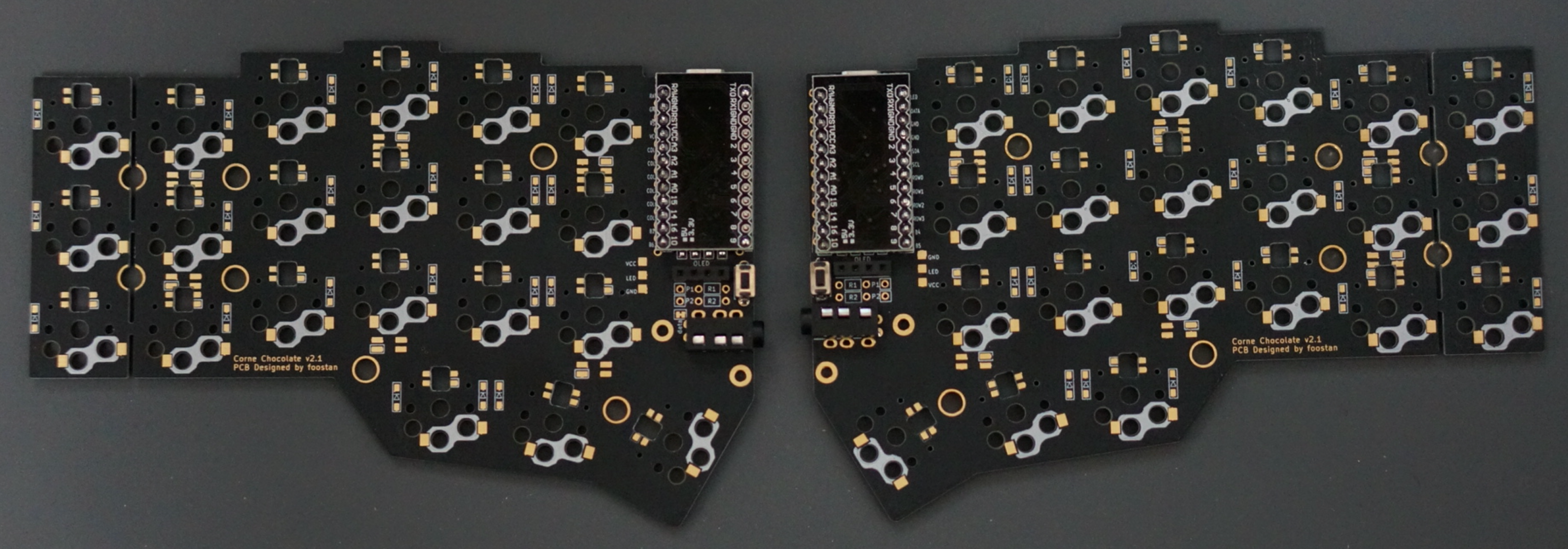
## Building
|
|
|
|
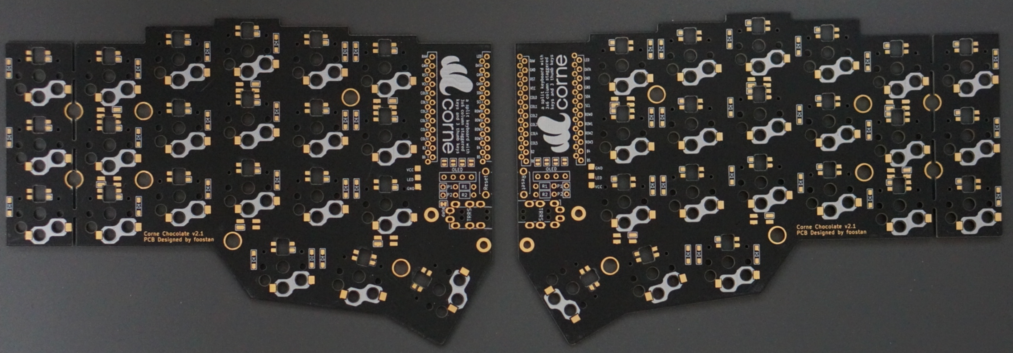
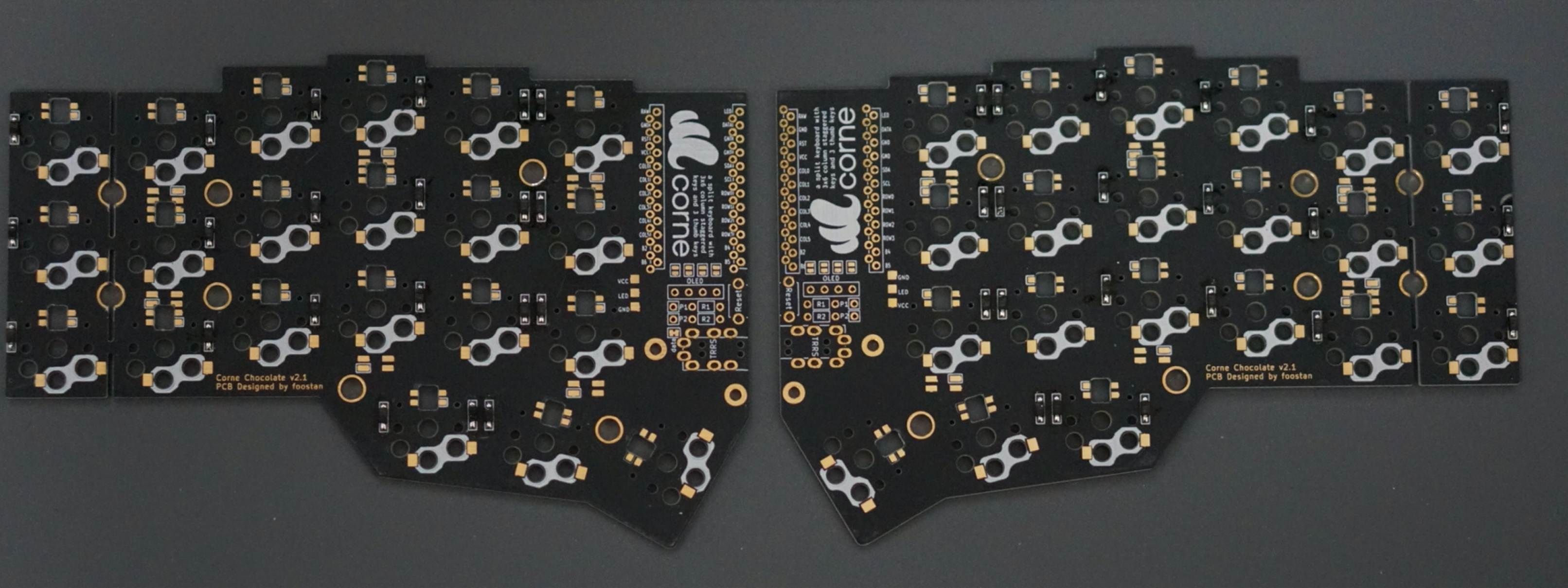
Since the PCB is reversible,
|
|
you first have to decide which one to use for the left side.
|
|
|
|
|
|
|
|
### Diodes
|
|
|
|
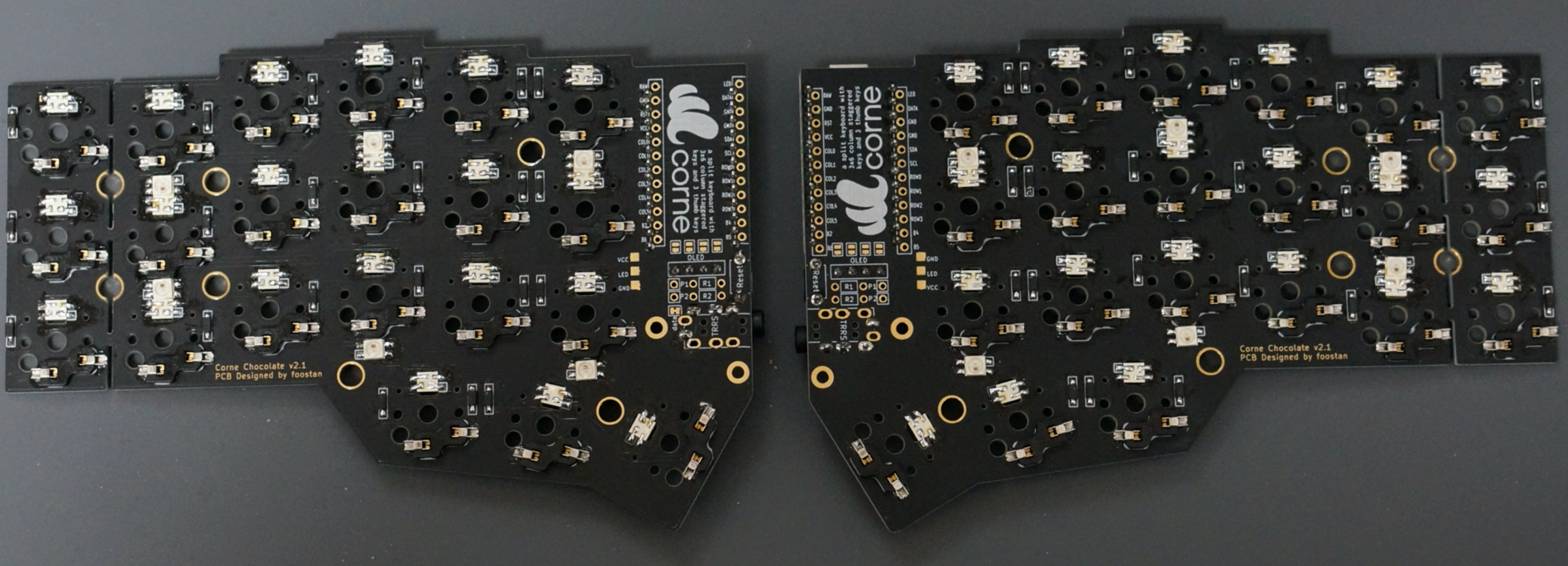
Solder the diodes to the PCB.
|
|
|
|
On Corne Cherry, it is up to you to choose which side to attach,
|
|
but with Corne Chocolate you must **be sure to attach it to the back**.
|
|
Mounting on the front will interfere with the top plate.
|
|
|
|
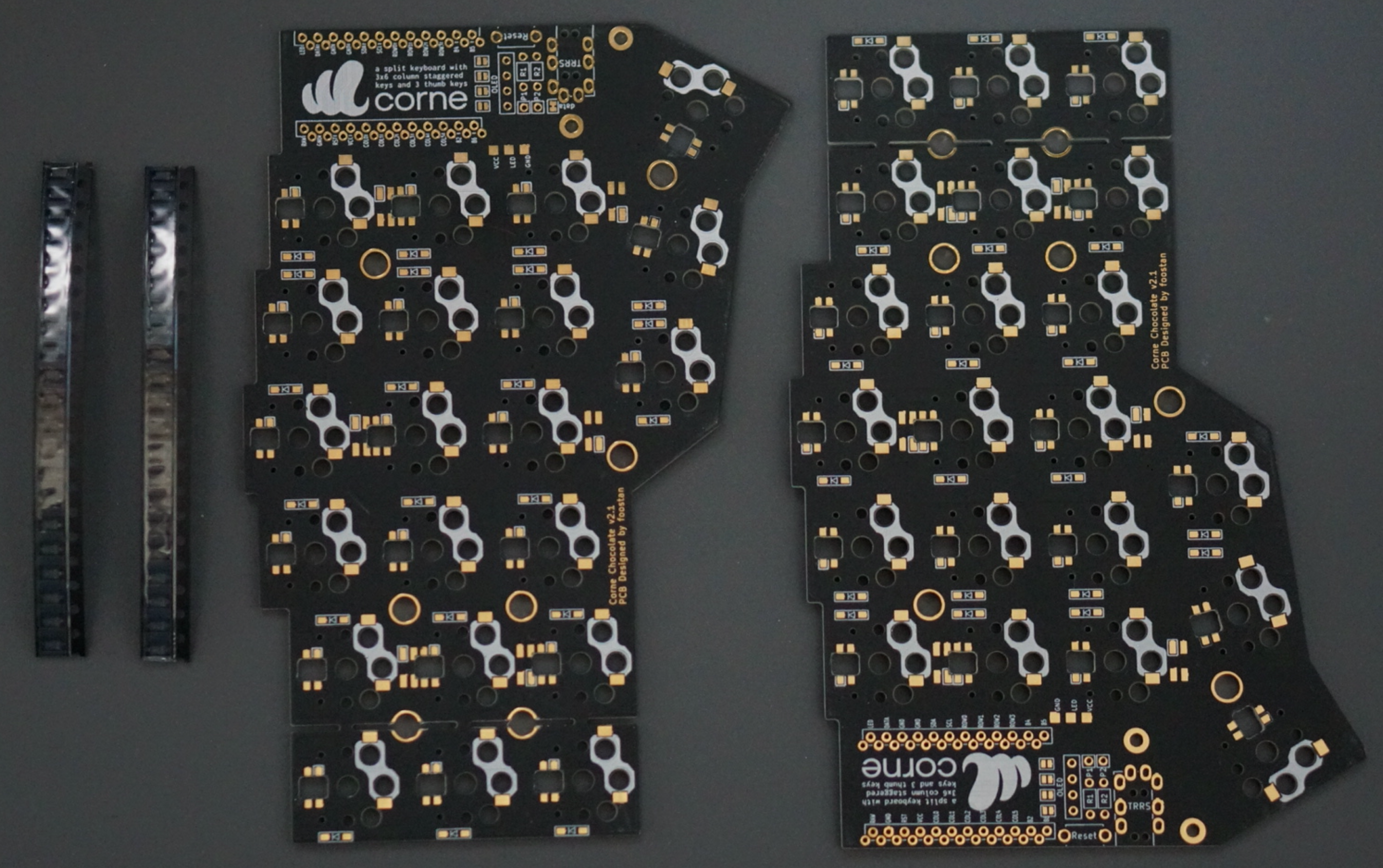
Since the diodes are very small,
|
|
it is easier to work with tweezers and inverted tweezers.
|
|
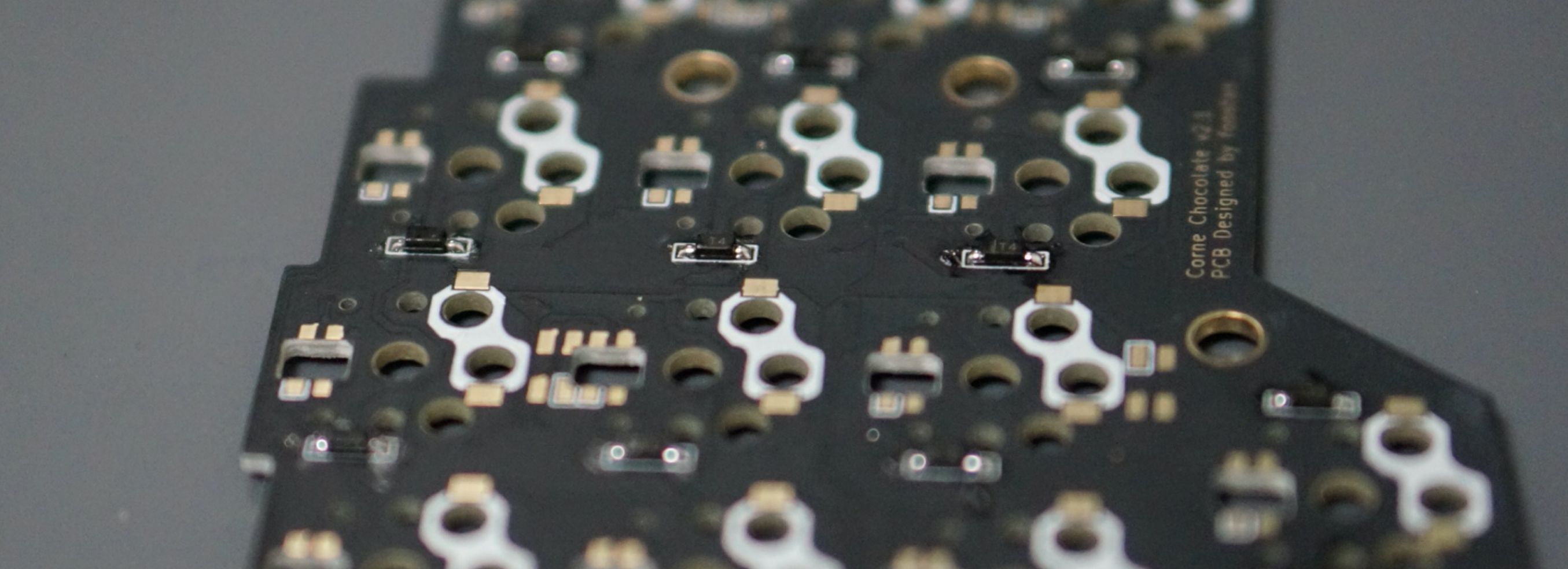
Since the **mounting orientation of the diode is crucial**,
|
|
it is possible to proceed smoothly
|
|
if you arrange the columns and rows to be mounted in advance,
|
|
as shown in the following photo.
|
|
|
|
|
|
|
|
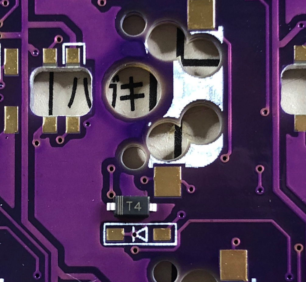
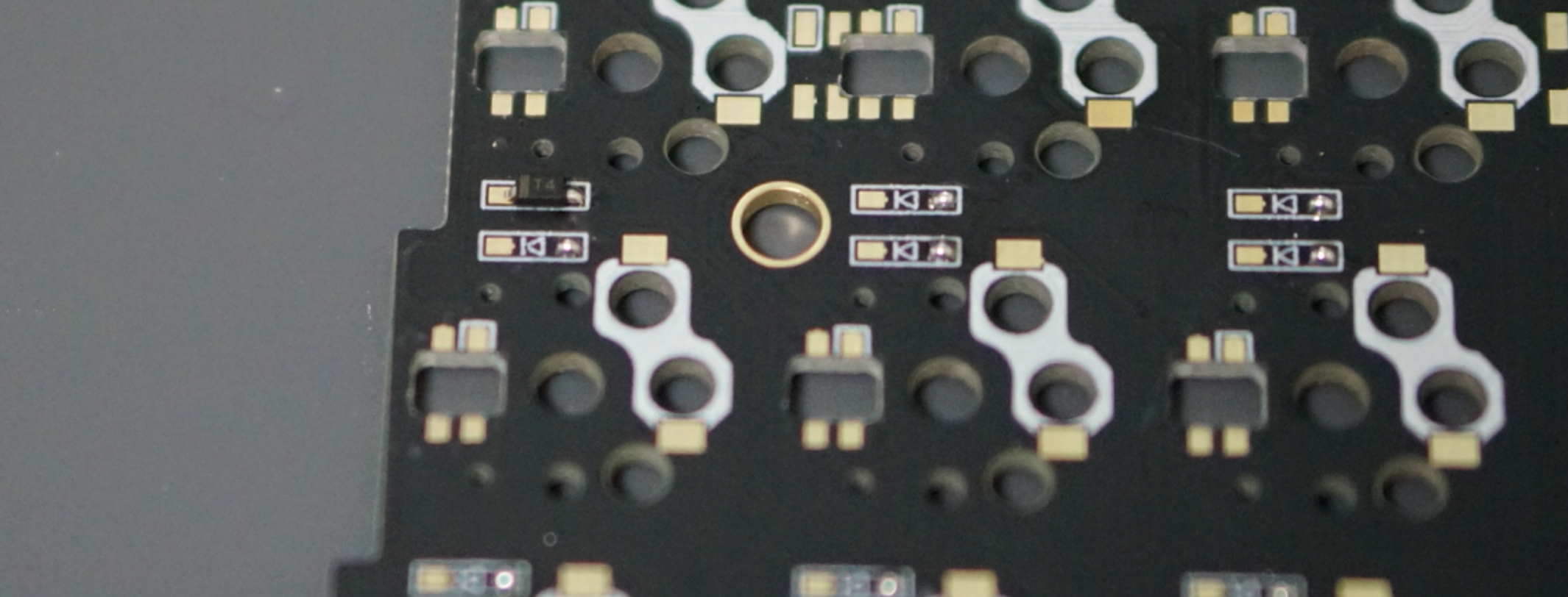
The orientation of the diode is as follows.
|
|
Attach the chip component so that the "|||" mark on the diode is facing the "|"
|
|
of the diode mark "|◁" on the PCB (image from Corne Cherry).
|
|
|
|
|
|
|
|
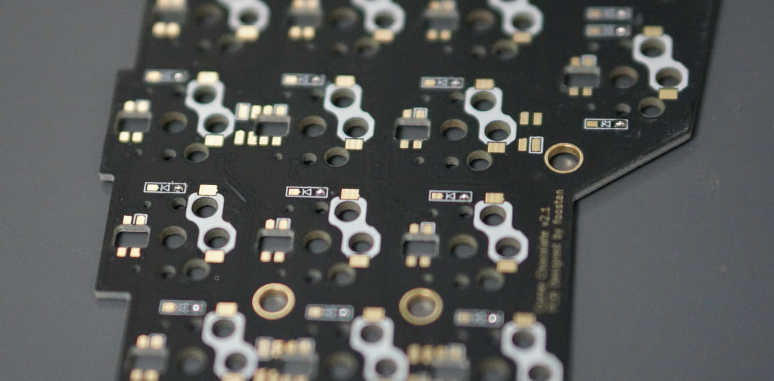
Tip for soldering on SMD parts:
|
|
First put solder only on the right side of the pad.
|
|
|
|
|
|
|
|
Next, solder one of the diodes by melting the solder you already put on the board.
|
|
At this time,
|
|
it is recommended to use [reverse-action tweezers](https://www.alimed.com/_resources/cache/images/product/70895A_850x480-pad.jpg),
|
|
so that you can hold the SMD part firmly without applying force,
|
|
and concentrate on alignment and soldering instead.
|
|
Also, if the soldering iron is too hot or the solder is touched too long,
|
|
the flux contained in the solder may evaporate and form an undesirable pile solder,
|
|
but since it can be repaired later,
|
|
so at this point you should only care about attaching parts.
|
|
It's okay.
|
|
|
|
|
|
|
|
Then solder the other pin.
|
|
Be careful not to apply too much solder,
|
|
as a small amount is sufficient.
|
|
If you have applied too much,
|
|
you can remove it with a suction pump, blotting wire
|
|
or by scooping it with a soldering iron.
|
|
|
|
|
|
|
|
If the amount of solder on the pre-soldering side is too small,
|
|
add more soldering,
|
|
and if it is pilled up,
|
|
apply flux from above and heat to clean.
|
|
|
|
|
|
|
|
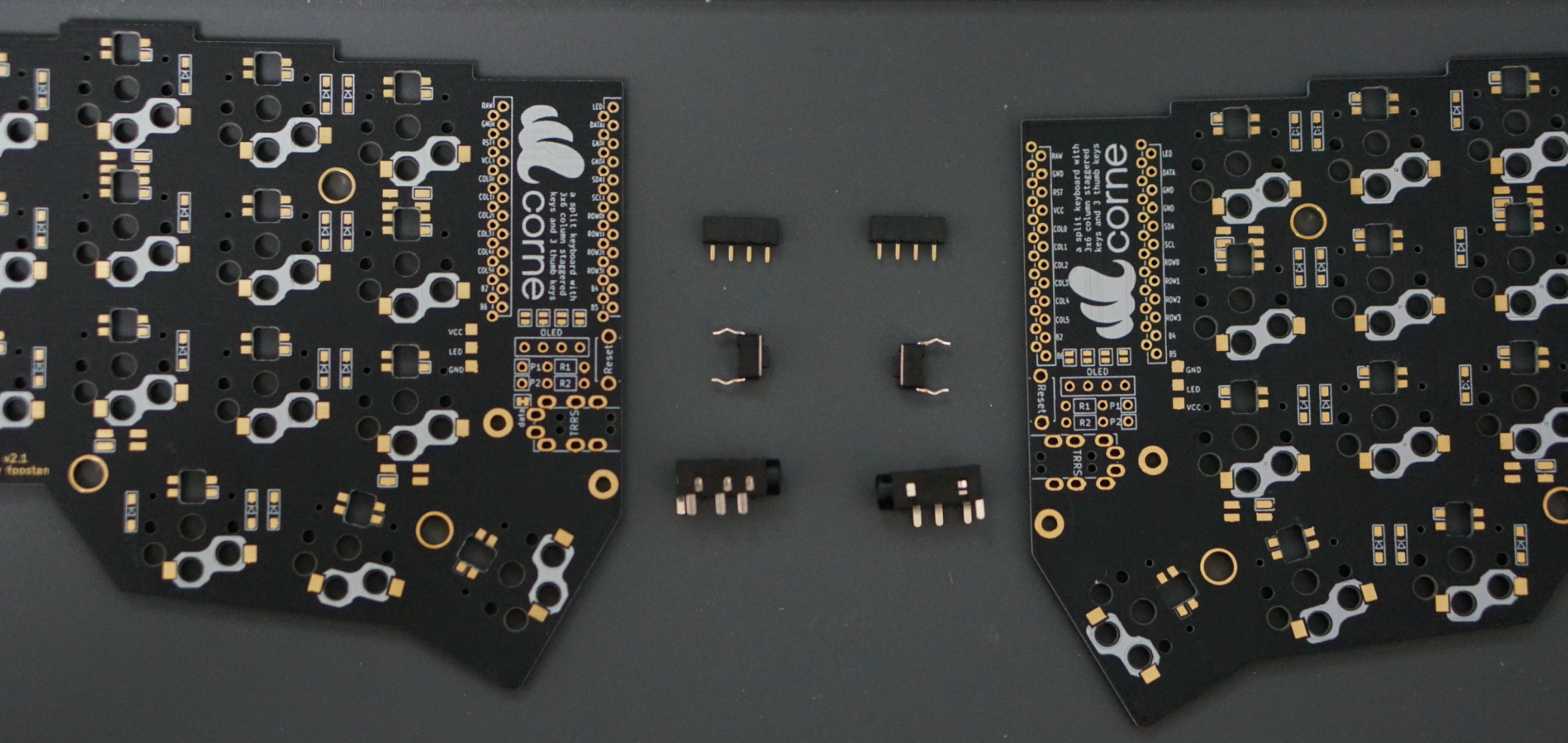
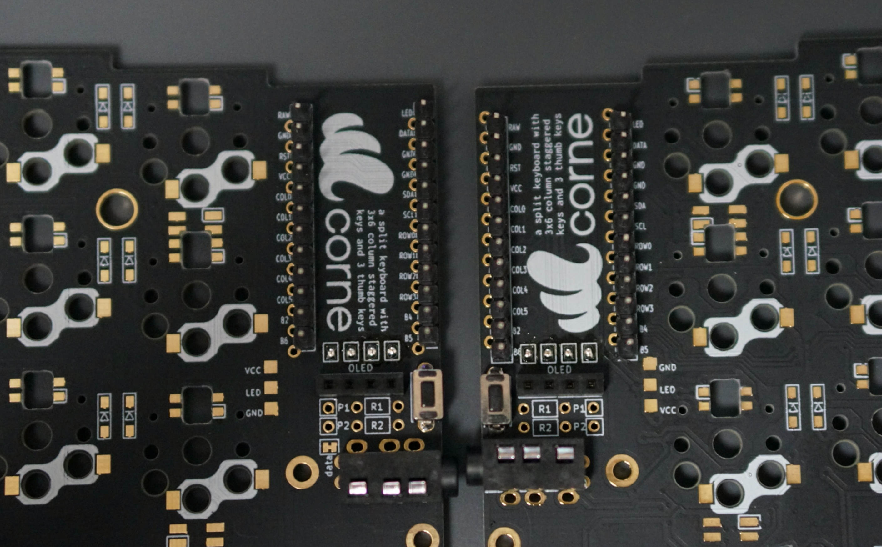
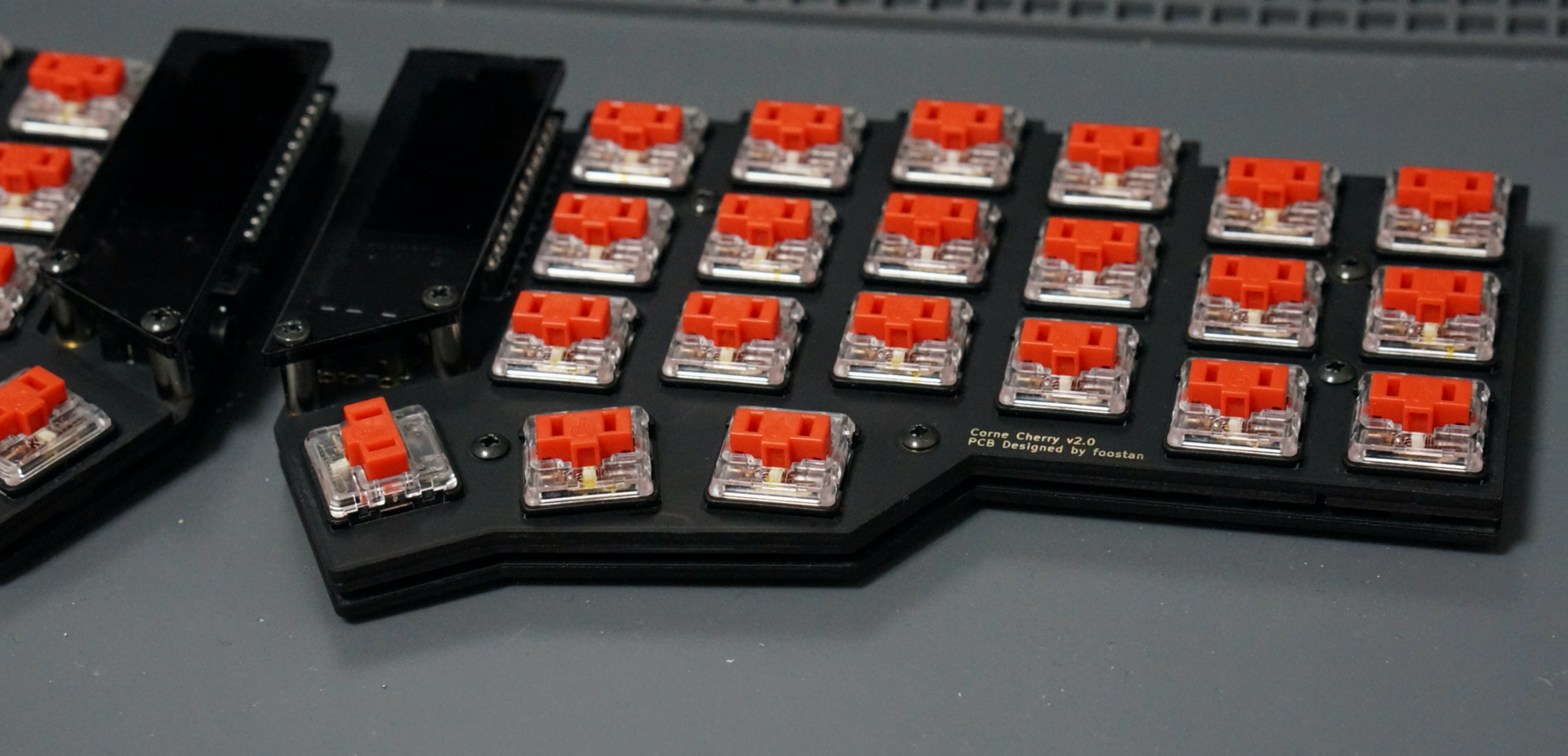
### TRRS jack, reset switch, pin socket
|
|
|
|
|
|
|
|
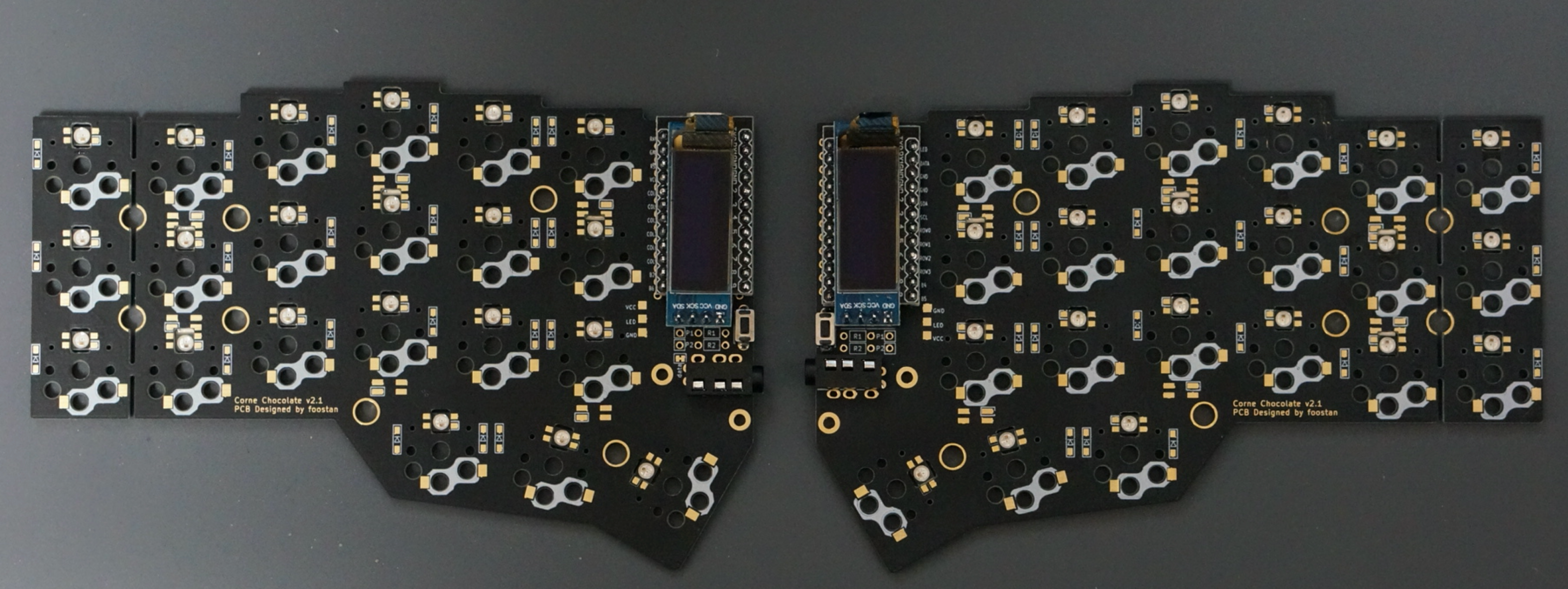
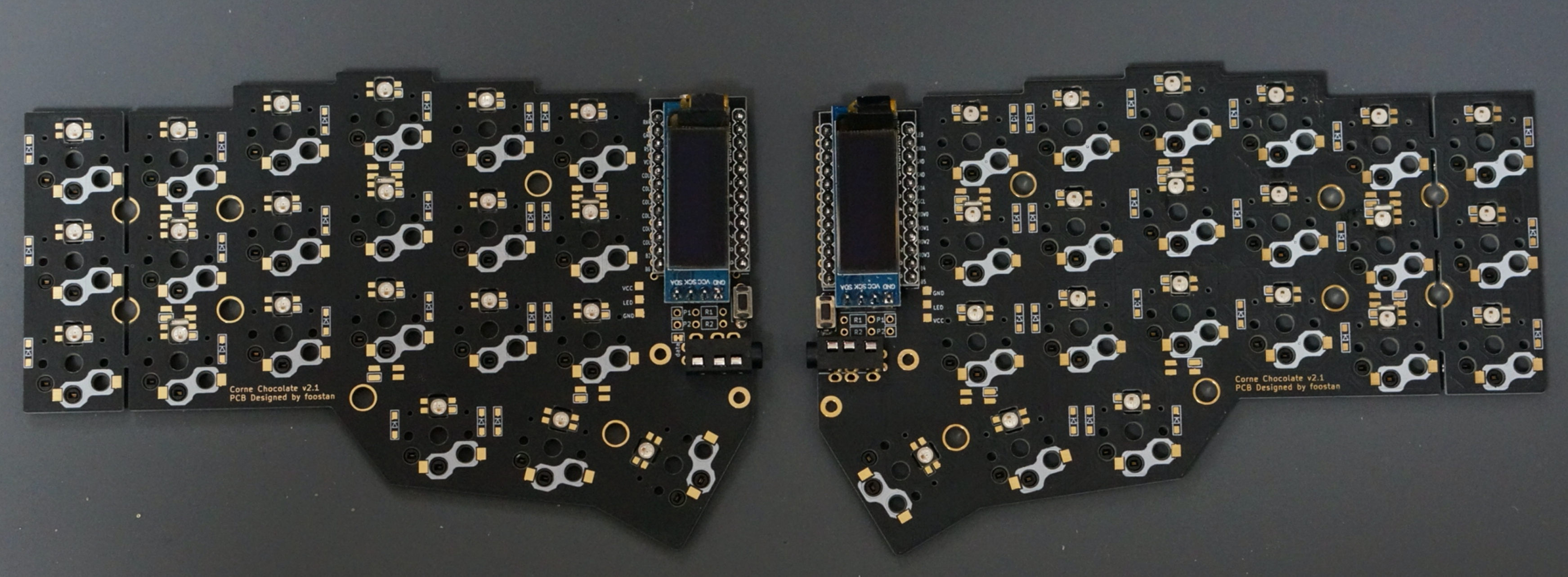
Solder the TRRS jack, reset switch and pin socket to the **front of the PCB**
|
|
as shown in the picture below.
|
|
Since the diode is attached on the back side,
|
|
it will be on the opposite side.
|
|
|
|
|
|
|
|
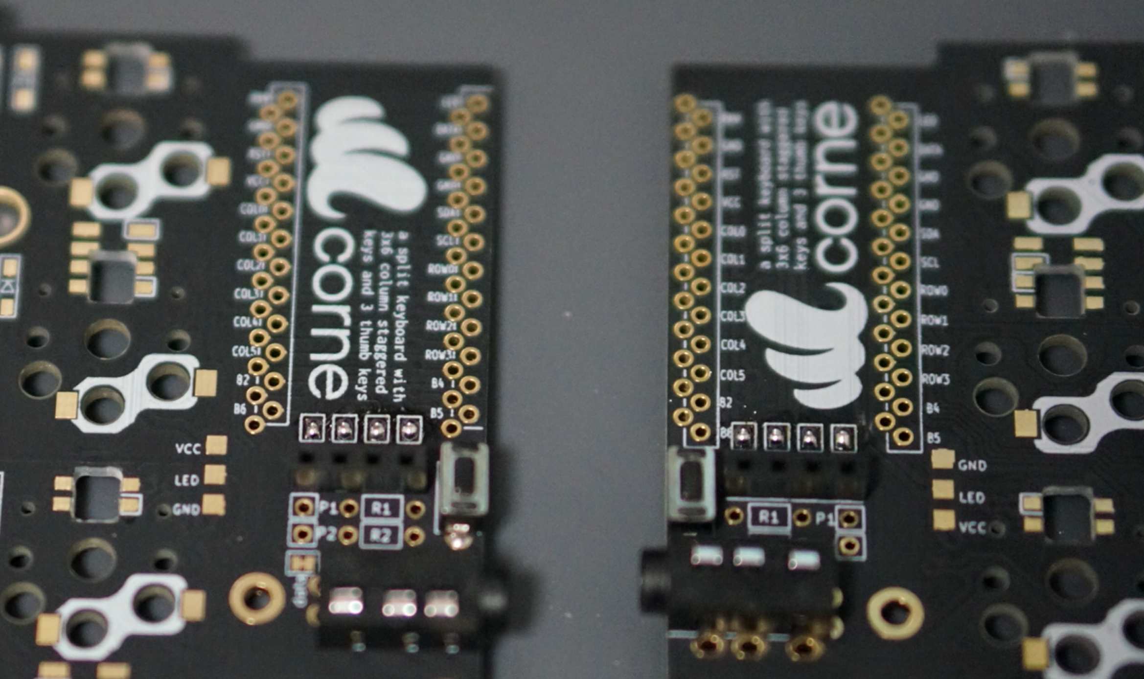
### Jumpers for OLED modules
|
|
|
|
When using an OLED module, use solder as jumpers (4 times per side) as follows.
|
|
**Please jumper only on the surface**.
|
|
|
|
|
|
|
|
If the jumper doesn't work,
|
|
you probably have a small amount of solder,
|
|
or the flux has vaporized.
|
|
If so, you can fix the jumper by applying more solder or separate flux.
|
|
|
|
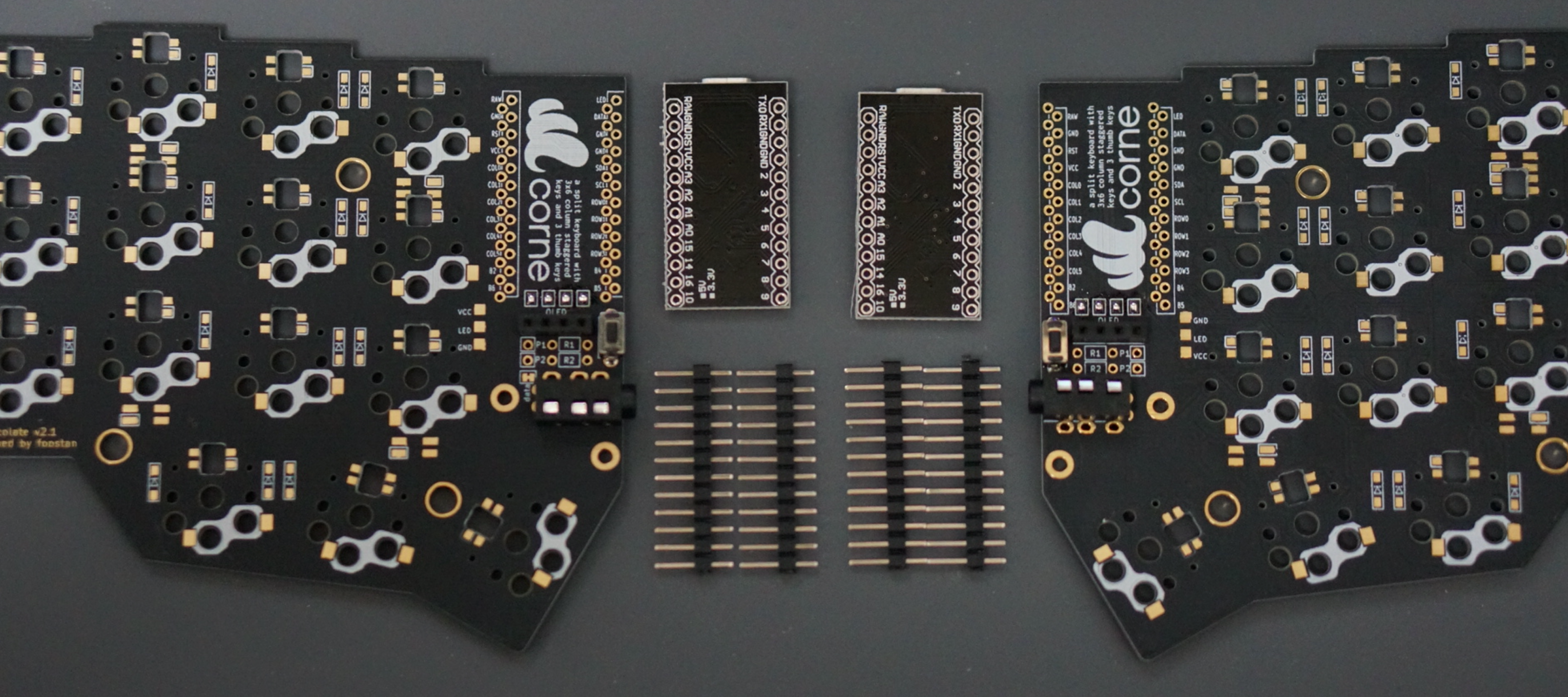
### Pro Micro
|
|
|
|
|
|
|
|
Solder the pin headers to the white frame
|
|
and solder the Pro Micro with back side up.
|
|
|
|
|
|
|
|
|
|
When using the spring-loaded pin headers,
|
|
please refer to the [Helix Build Guide](
|
|
https://github.com/MakotoKurauchi/helix/blob/master/Doc/buildguide_en.md#pro-micro).
|
|
|
|
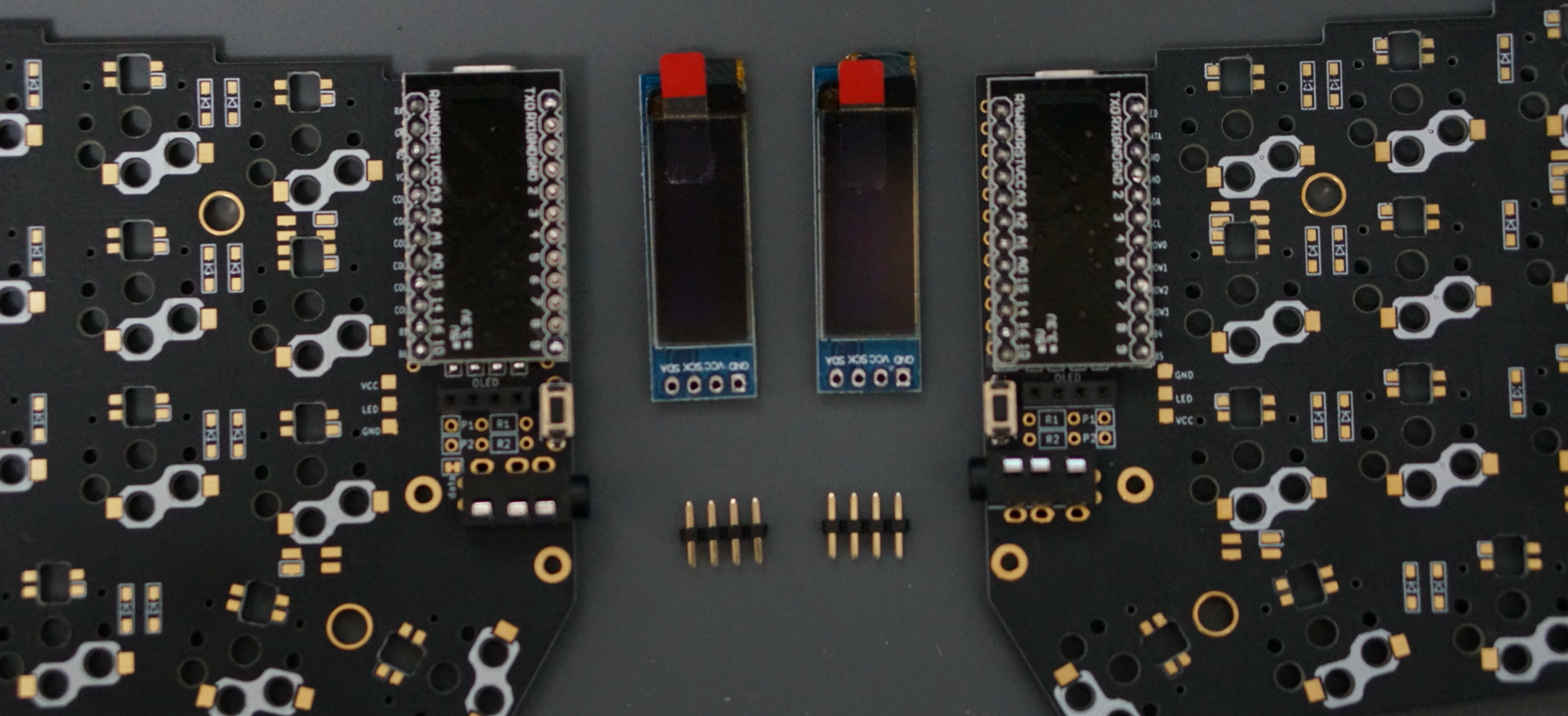
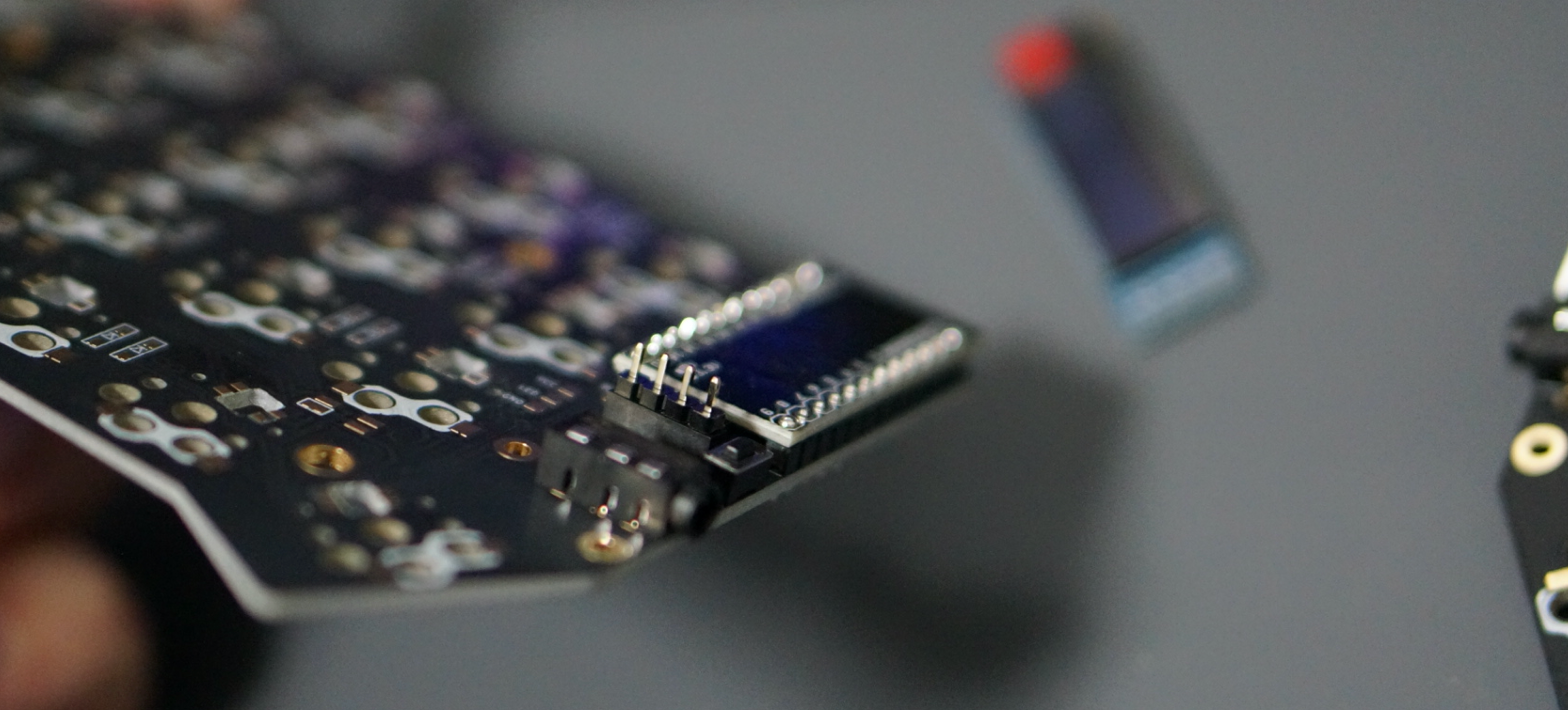
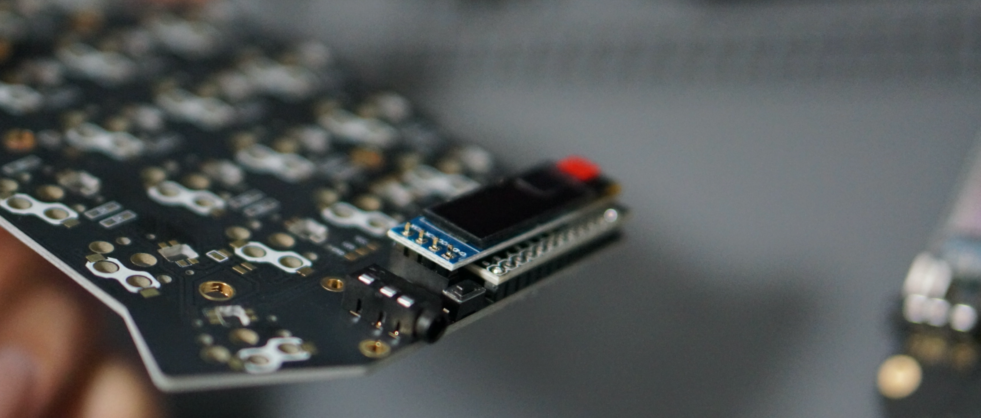
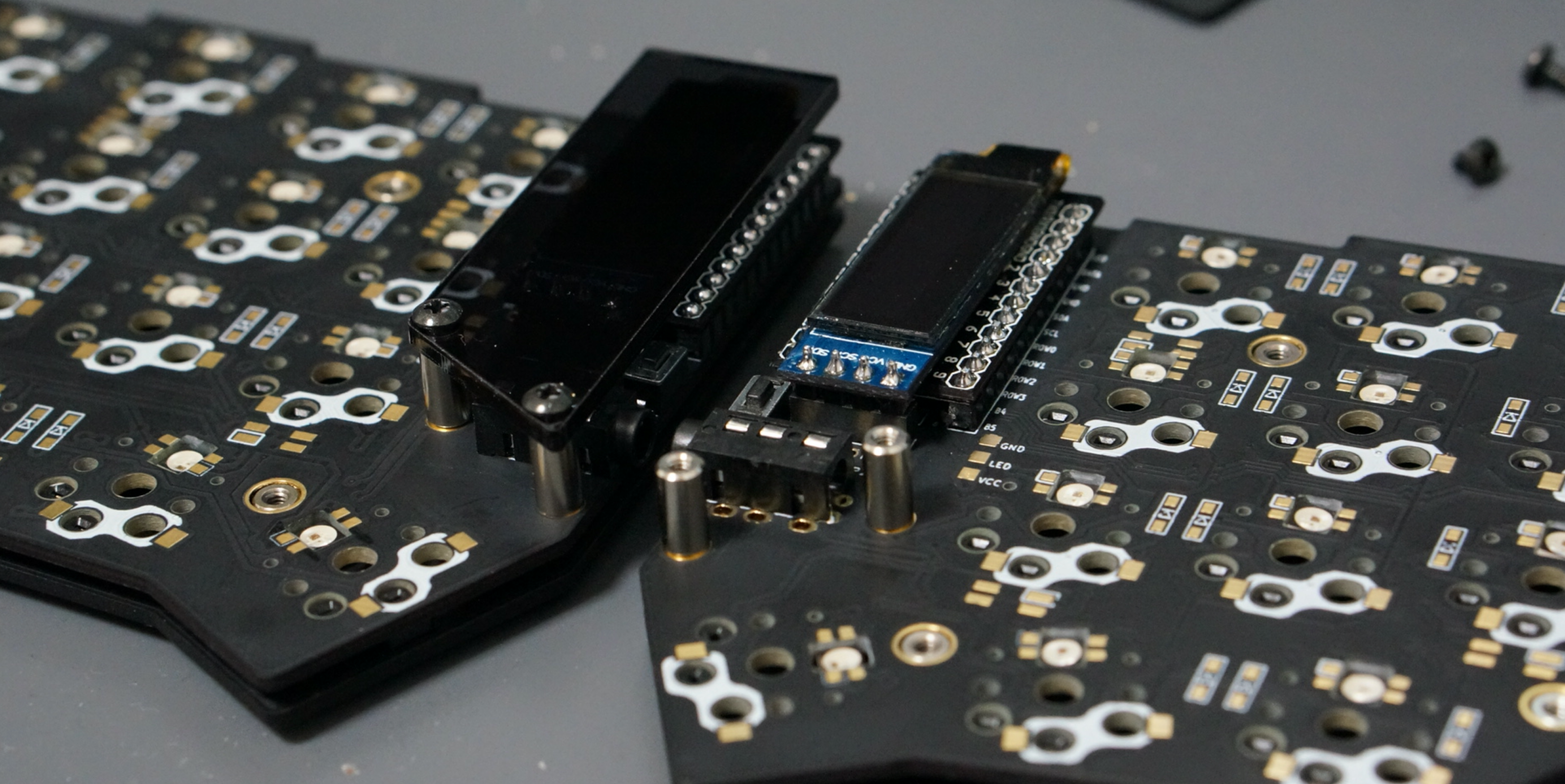
### OLED module
|
|
|
|
|
|
|
|
Insert the pin header into the OLED pin socket first,
|
|
then solder the pin header and the OLED module.
|
|
At this time,
|
|
make sure that the OLED module sits tightly on the socket
|
|
while holding it down with your finger,
|
|
because it tends to stick out easily.
|
|
|
|
|
|
|
|
|
|
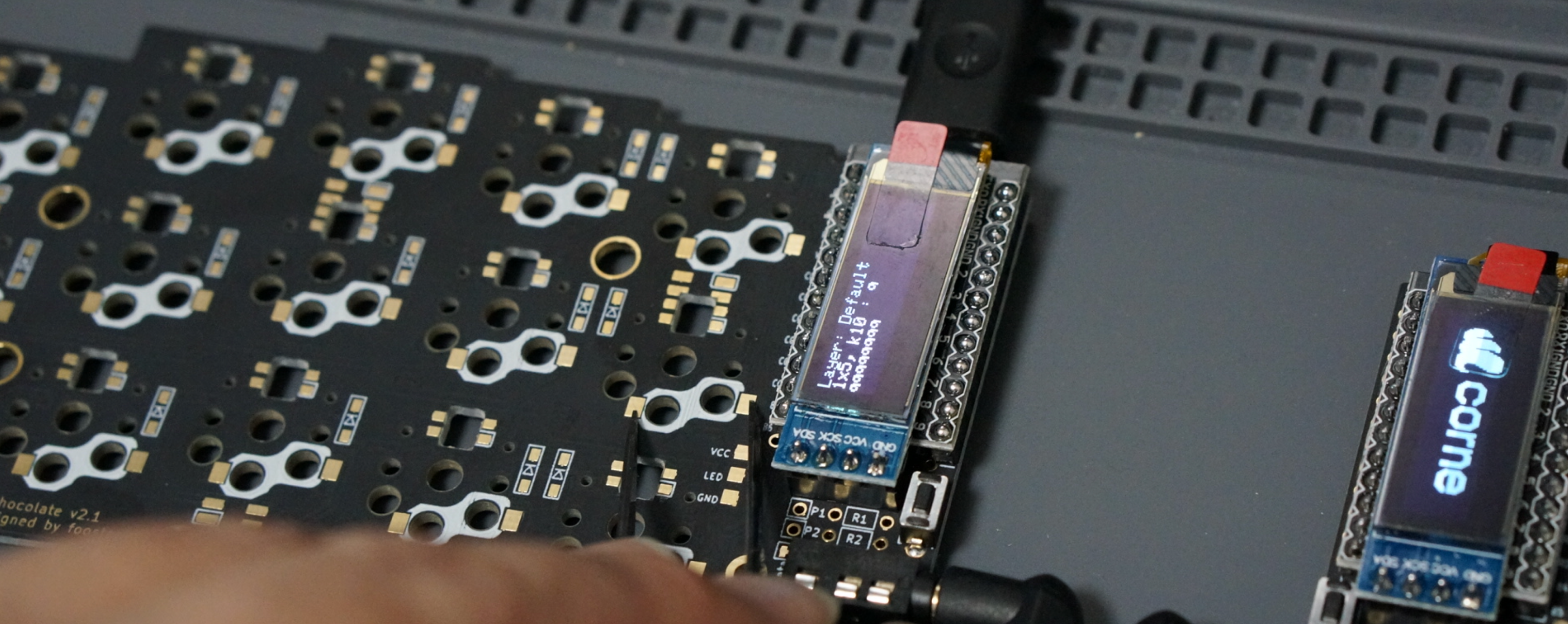
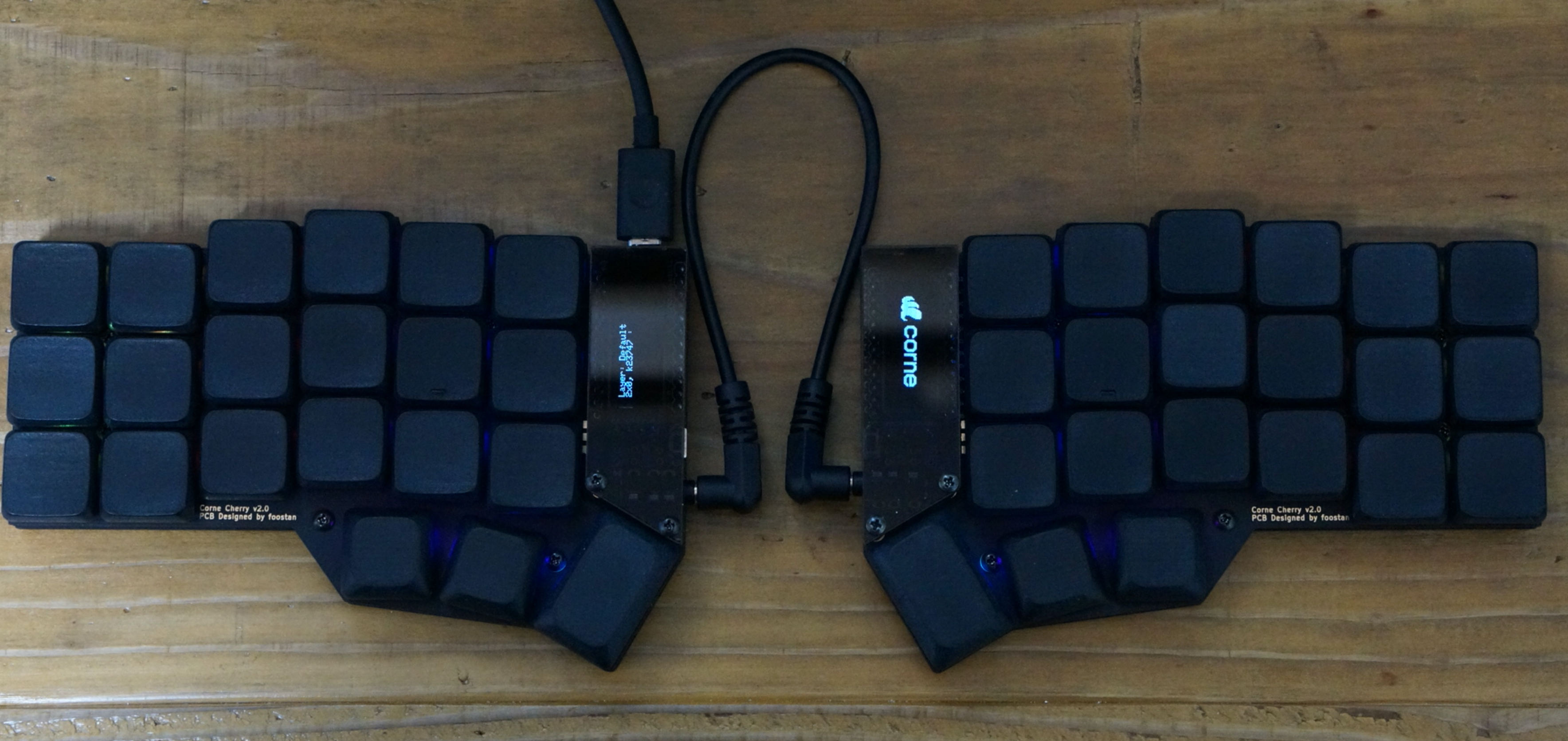
### Operation check
|
|
|
|
We recommend that you check the operation at the stage
|
|
where the Pro Micro and OLED modules are attached
|
|
(it is difficult to isolate the problem at the end).
|
|
|
|
Before checking the correct operation,
|
|
flash the crkbd firmware to the Pro Micro
|
|
by referring to the [Firmware](#firmware) section below
|
|
(be sure to insert it on both sides).
|
|
|
|
Operation confirmation is performed
|
|
by connecting the left hand side to a PC with Micro USB
|
|
and connecting the left hand side and the right hand side with a TRS cable.
|
|
Since there may be a defect such as a jack,
|
|
make sure to connect the left and right
|
|
instead of one by one before checking the operation.
|
|
If you have done this correctly,
|
|
short-circuit the pad to attach the PCB socket with tweezers,
|
|
and the key pressed on the OLED module will be displayed.
|
|
|
|
|
|
|
|
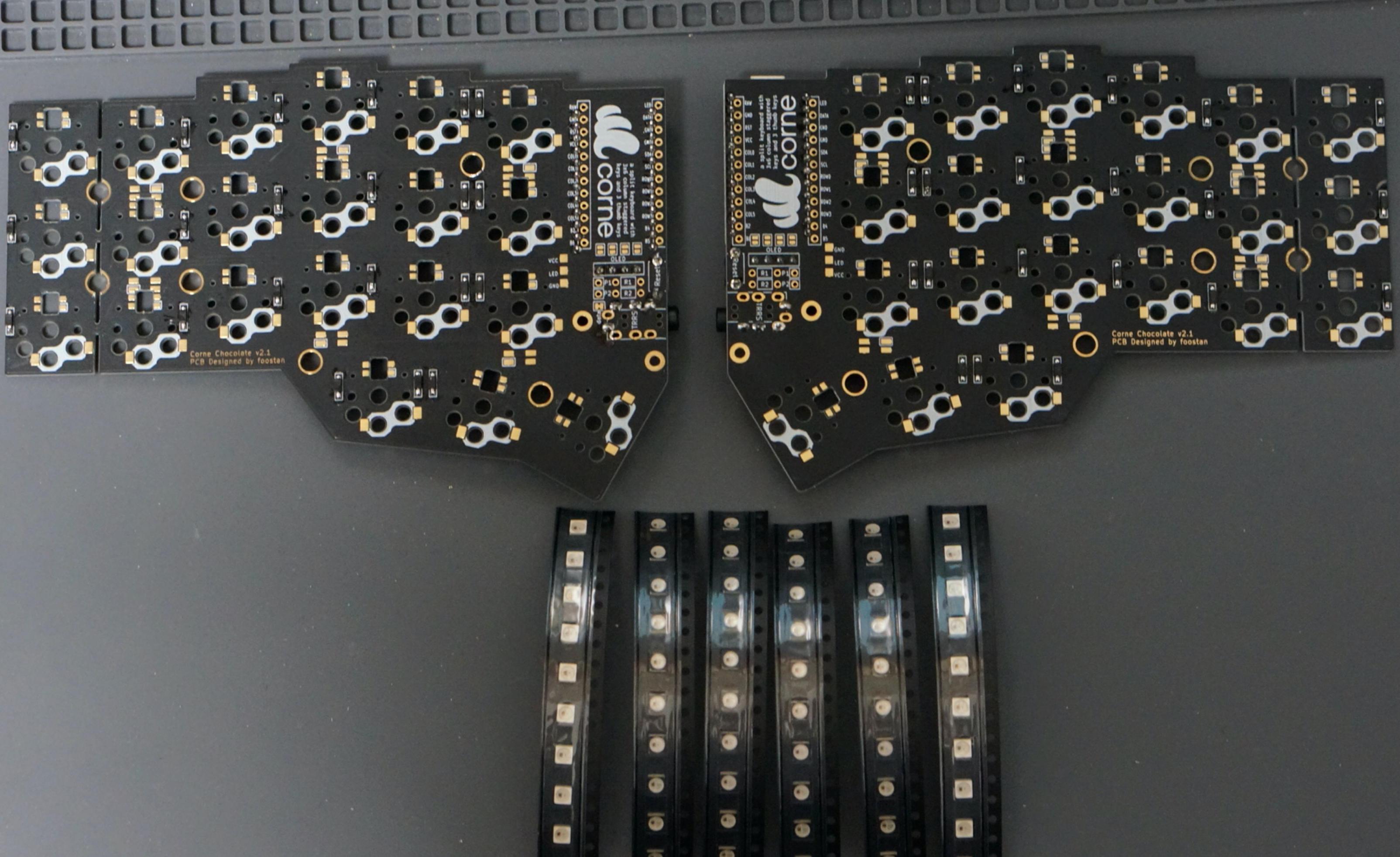
## LED (optional)
|
|
|
|
|
|
|
|
I will install SK6812MINI.
|
|
The LED can be mounted even after completion,
|
|
so if you are worried about mounting it,
|
|
we recommend that you skip this chapter and complete it first.
|
|
|
|
SK6812MINI is very heat sensitive and breaks easily.
|
|
We recommend using a soldering iron with a temperature control function
|
|
and operating at a temperature of about 220°C to 270°C.
|
|
Even if the temperature is set that low,
|
|
the LED will be damaged if the iron is left on it for a long time,
|
|
so try to solder as quickly as possible.
|
|
Solder four LEDs at a time,
|
|
but we recommend soldering two at a time instead of four at a time
|
|
to prevent the LED temperature from rising,
|
|
as this will make it less likely to overheat.
|
|
|
|
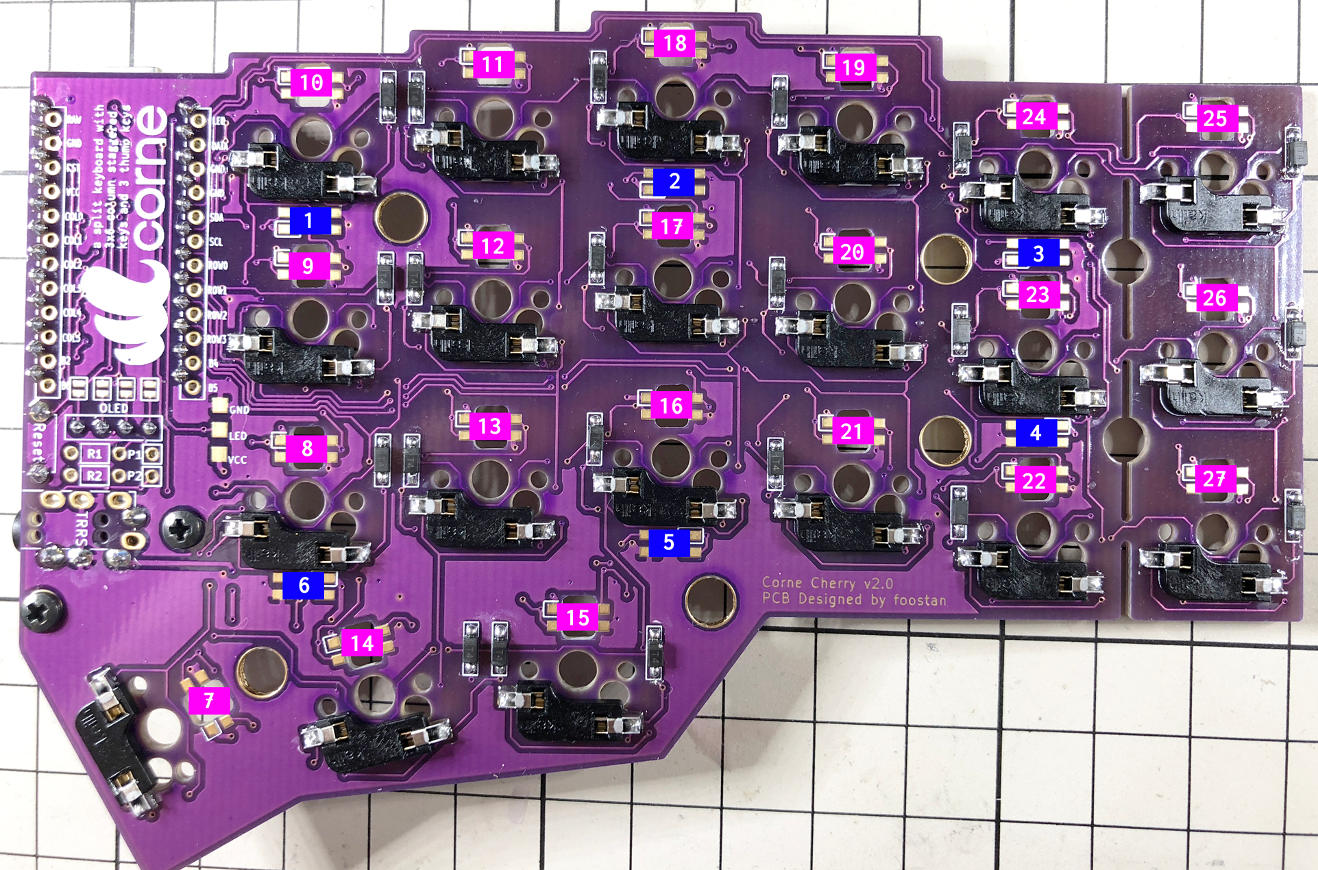
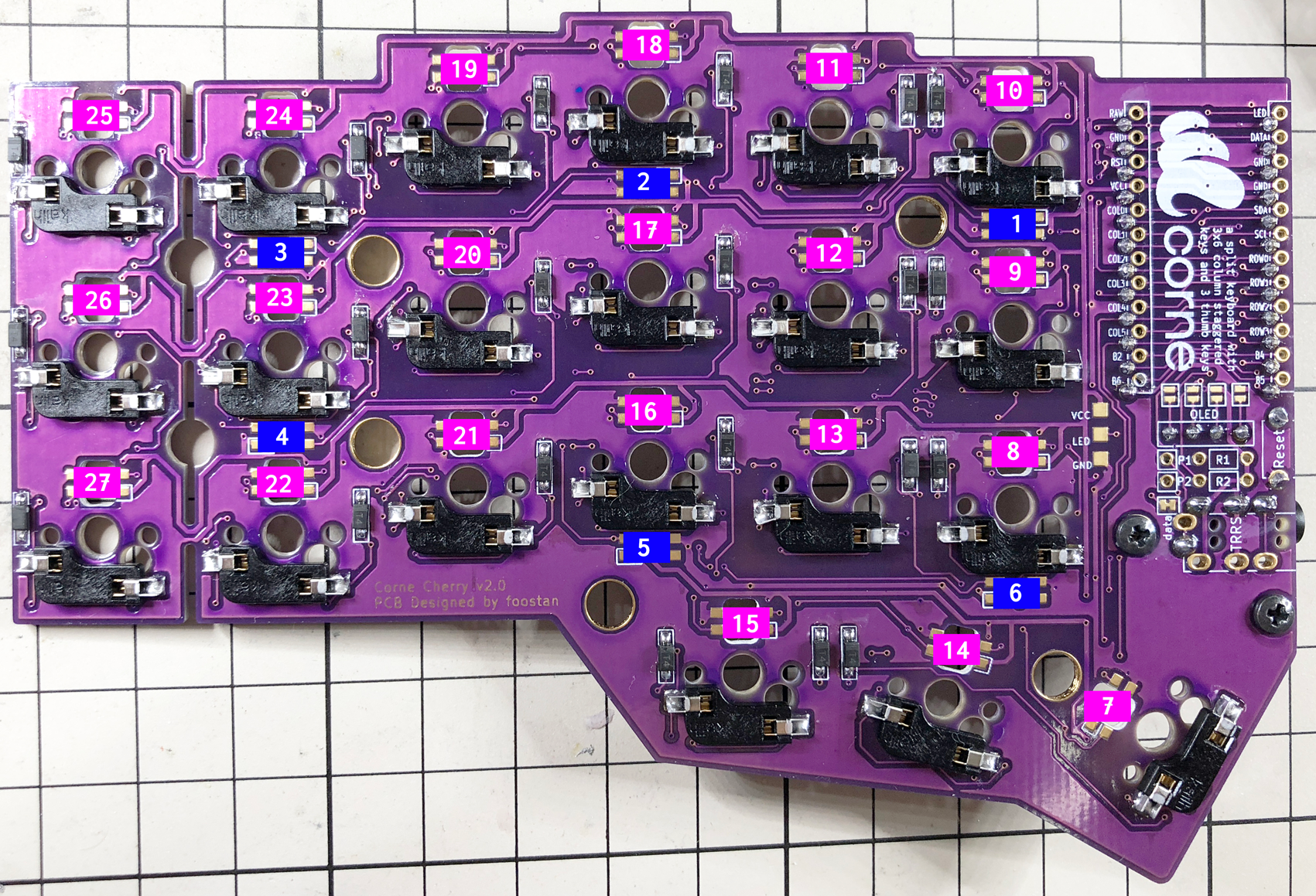
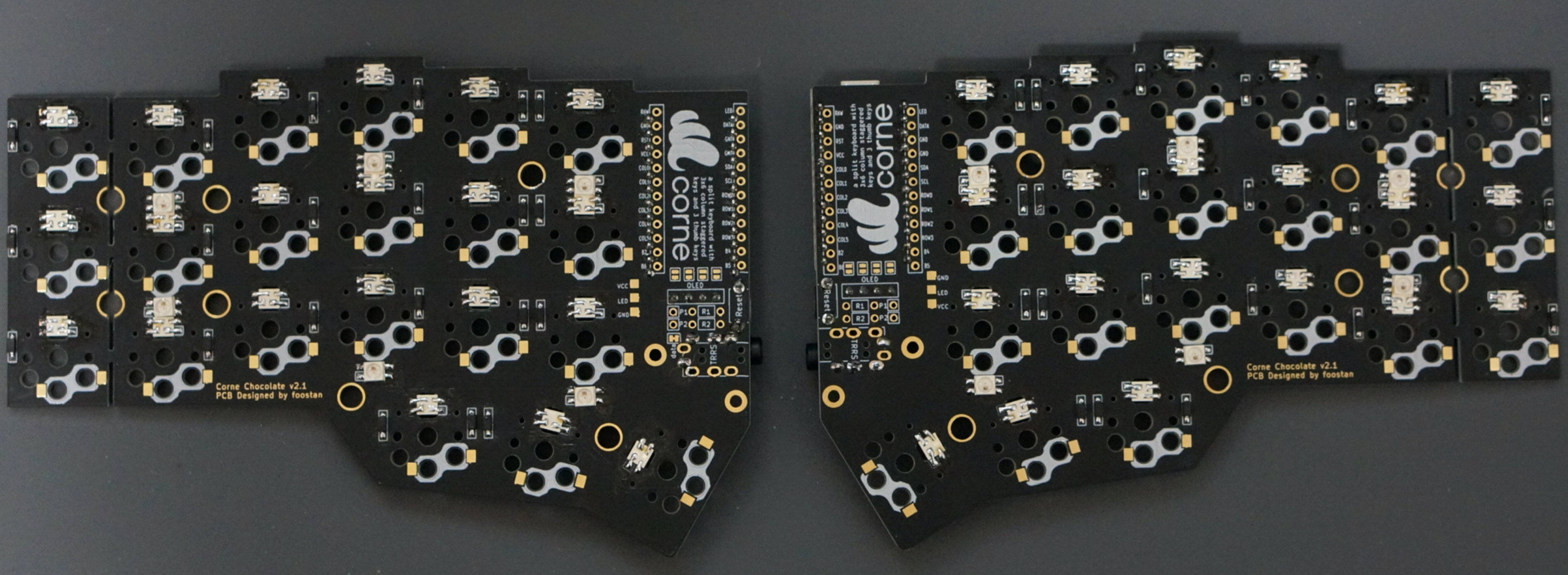
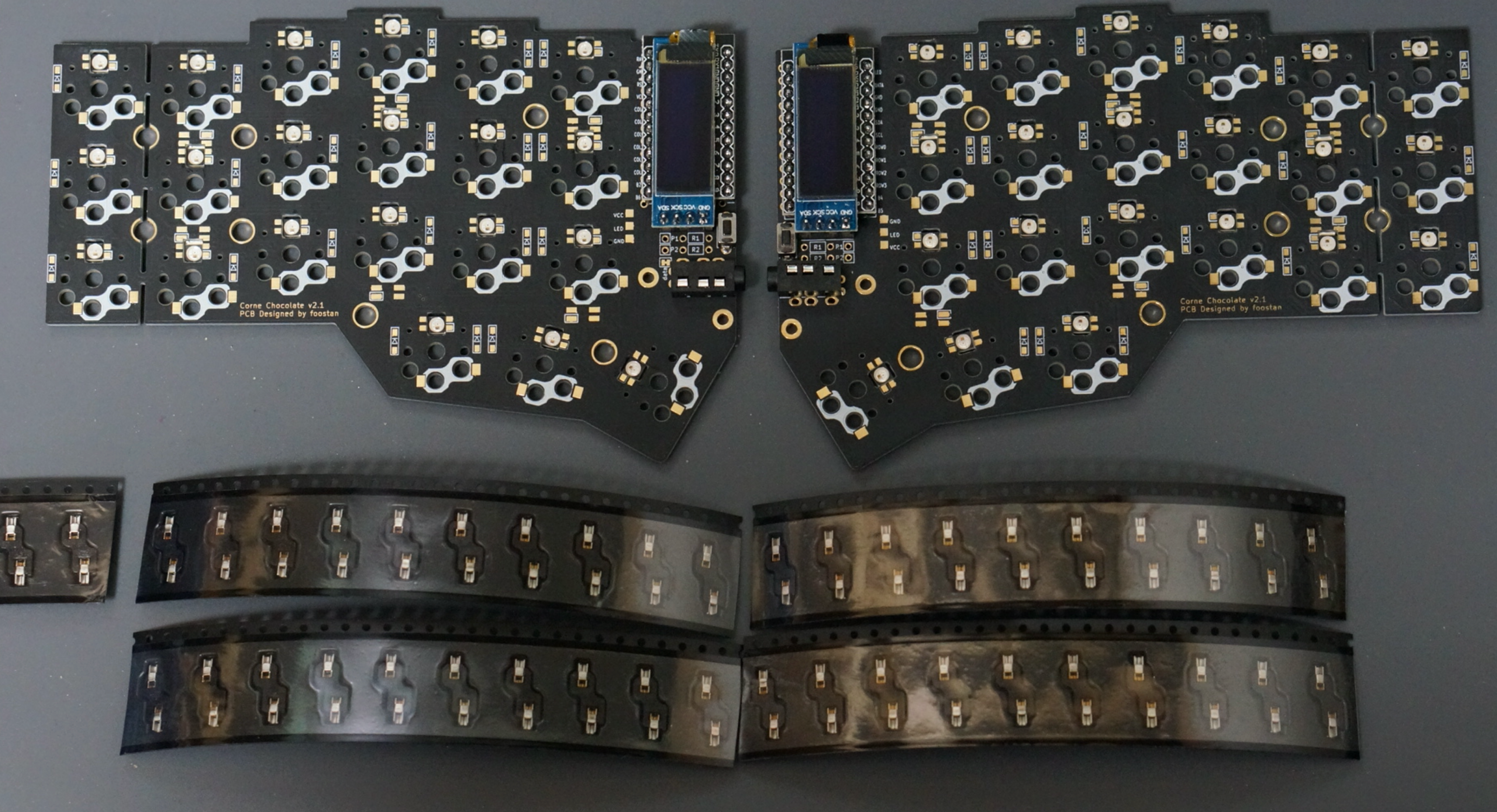
First, check the mounting position.
|
|
|
|
Solder 1 - 6 so that the back side (under-glow) shines,
|
|
7 - 27 so that the front side (back-light) shines.
|
|
Below is the location to attach the LED (image from Corne Cherry).
|
|
|
|
|
|
|
|
|
|
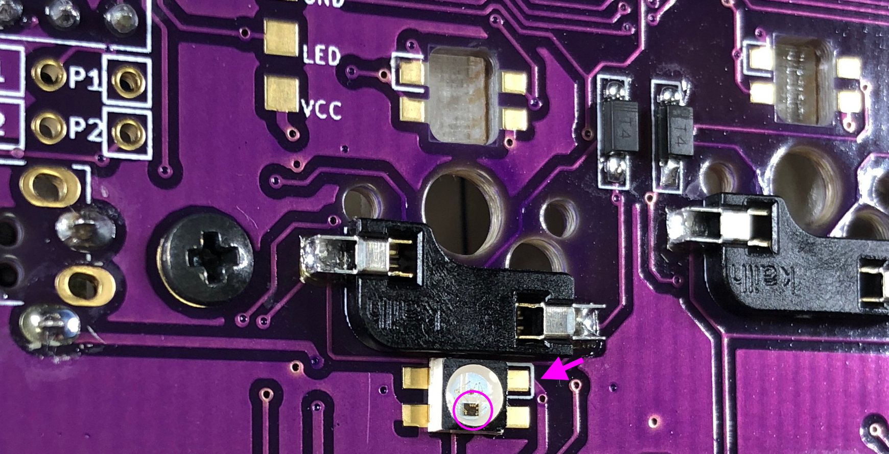
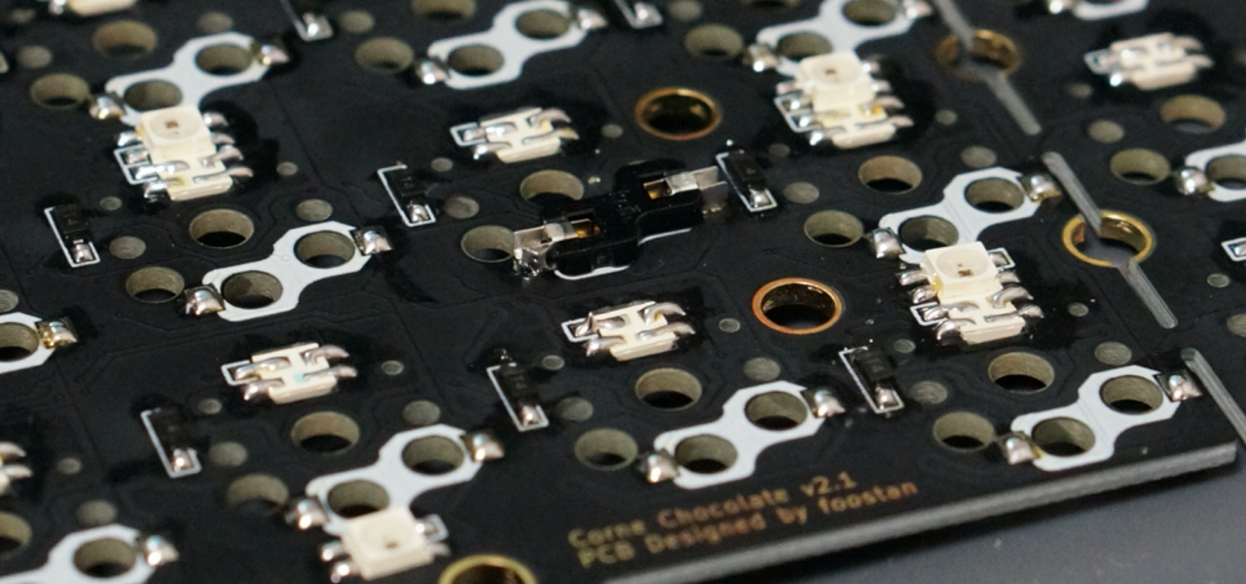
For LEDs 1 to 6,
|
|
solder the part so that the black part circled below is on the bottom
|
|
and the silk mark indicated by the arrow is on the top.
|
|
Note that the direction changes between 1 - 3 and 4 - 5.
|
|
|
|
|
|
|
|
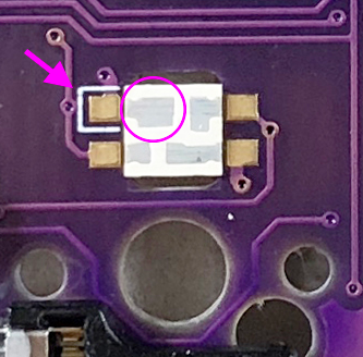
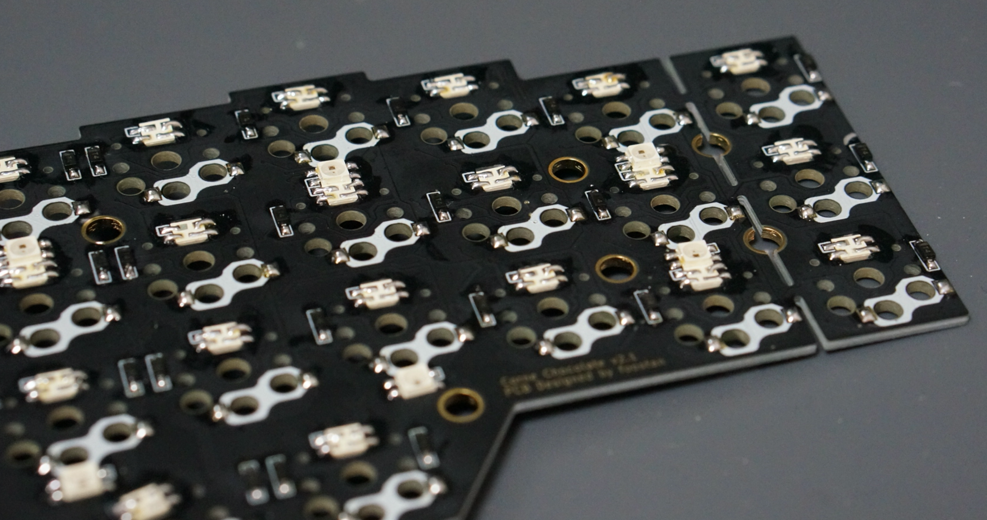
For 7 - 27,
|
|
perform soldering so that the largest pad surrounded by a circle
|
|
and the silk mark indicated by an arrow are adjacent to each other,
|
|
as shown below.
|
|
|
|
|
|
|
|
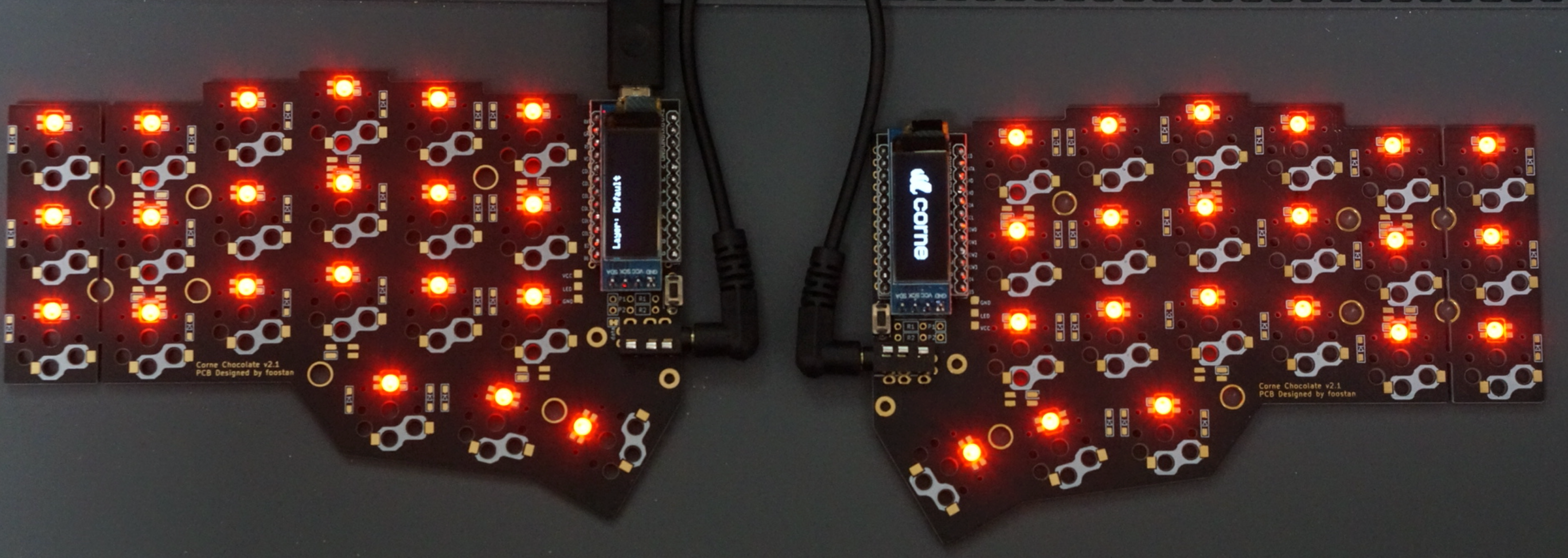
If everything was successfully soldered,
|
|
it will glow as follows.
|
|
If the LED lights only halfway,
|
|
the LEDs are connected in the order of the numbers.
|
|
Therefore, it is likely that the LED that does not emit light
|
|
or the previous LED are incorrectly soldered or damaged.
|
|
|
|
|
|
|
|
|
|
|
|
### Kailh PCB Socket
|
|
|
|
|
|
|
|
Apply solder to the pads on both sides on the back.
|
|
It is difficult to add it later,
|
|
so please fill it up beforehand.
|
|
|
|
|
|
|
|
Insert the socket and melt the solder.
|
|
At this time,
|
|
hold the socket with tweezers or your fingers so that the socket sticks to the board.
|
|
|
|
|
|
|
|
The soldering is now complete.
|
|
|
|
|
|
|
|
|
|
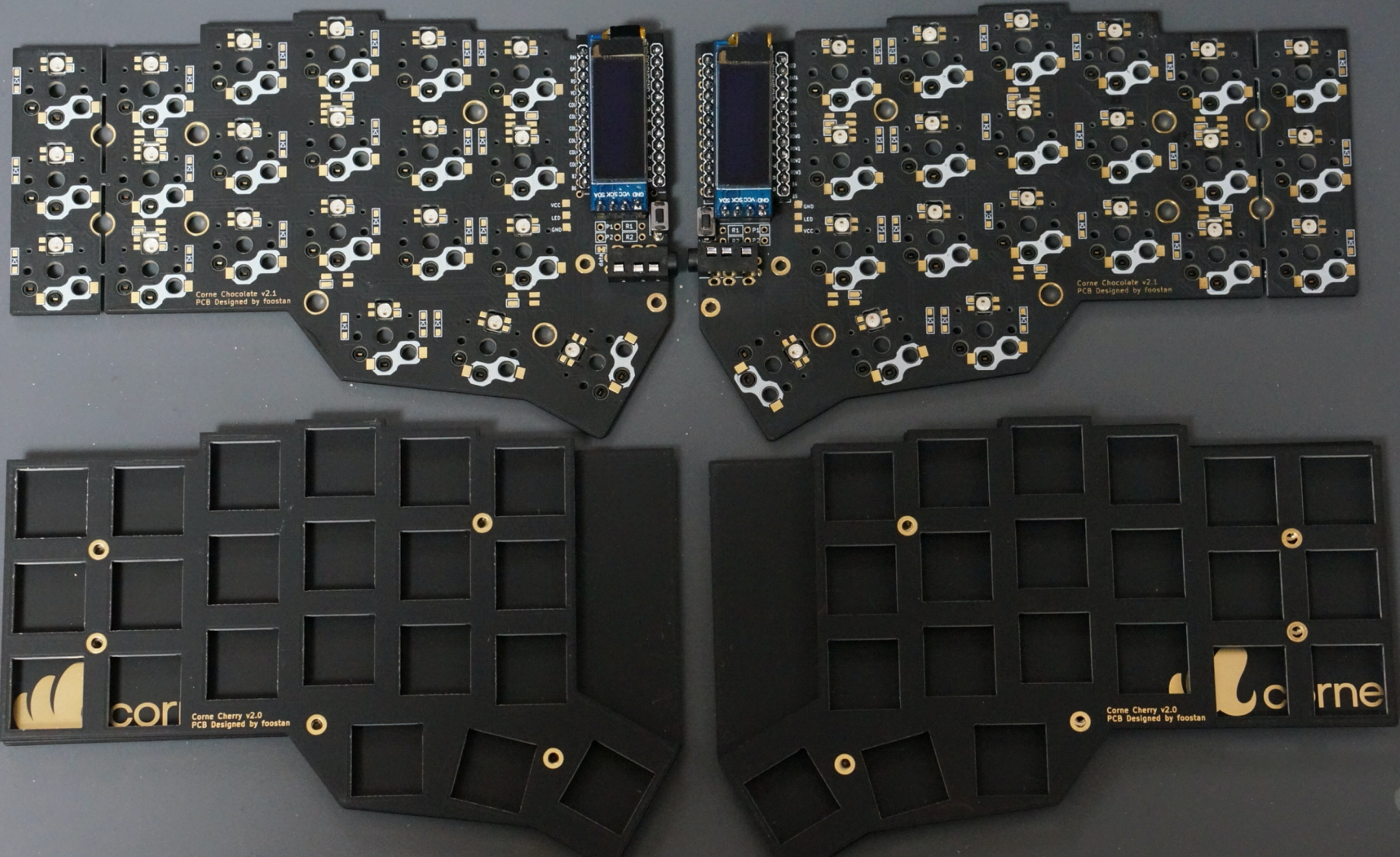
### Plate, switch
|
|
|
|
|
|
|
|
Use 4.5mm spacers for the top and bottom plates
|
|
and 9mm spacers for the OLED.
|
|
|
|
|
|
|
|
In addition,
|
|
it is recommended to paint the side of the plate with a black marker
|
|
because it looks better.
|
|
|
|
|
|
|
|
## Firmware
|
|
|
|
See below to flash the firmware to the ProMicro. \
|
|
<https://github.com/foostan/crkbd/blob/master/doc/firmware_en.md>
|
|
|
|
This is the end.
|
|
|
|
|