8.3 KiB
bacBus v4r1
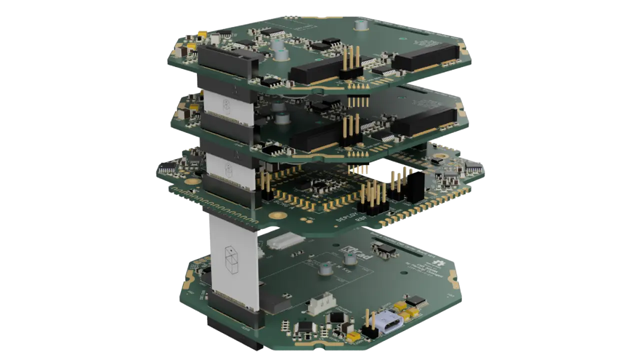
bacBus is a custom M.2-based Key-M interconnect standard used to connect subsystems within the Build a CubeSat (BAC) architecture.
The system is designed to have two largely identical and independent buses: bacBus A on the Ym side and bacBus B on the Yp side. The buses can be used for redundancy or for independent capabilities, such as dedicating an entire bus to payload operations. This adds flexibility to the architecture.
The currently available boards support a single bacBus only, with the exception of the EPS, which supports both A and B. Due to the symmetrical nature of the architecture, boards can be connected to either bus. Future iterations will include dual-bacBus capable boards.
The BAC architecture supports a 5mm PCB pitch, hence the interconnect boards are made lengths of 12.5mm to 52.5mm with increments of 5mm:
- 12.5mm
- 17.5mm
- 22.5mm
- 27.5mm
- 32.5mm
- 37.5mm
- 42.5mm
- 47.5mm
- 52.5mm
Longer lengths are possible (feel free to open an issue). KiCad projects for the currently available lengths can be found in the interconnect folder, Gerber files are available in the releases tab.
To reach from the EPS to the first board on the Zm side, the 32.5mm long interconnect is adequate. Single-bacBus PCBs offer a passthrough on the unconnected side – the same can be implemented on custom boards or models. For PCB-to-PCB distances of less than 5mm, the use of common board-to-board connectors is recommended (pin headers, mezzanine connectors). Search the structure repo release section for "PCB", "Mezzanine" and "Module Volume" for starting points.
Key Changes in v4r1
Version v4r1 introduces a simplified and more robust system architecture with CAN-based intra-satellite communication, improved power distribution, and additional system-wide control and safety signals.
Redundant CAN architecture
- All intra-sat communication now uses dual redundant CAN buses
- Legacy buses (I2C, SPI, etc.) have been removed from the interconnect
- CAN routing has been optimized for node placement and signal integrity
Improved power distribution
- VBAT is now exposed for power delivery, not only voltage sensing
- Improved routing for power rails on the EPS
- Dedicated auxiliary rail support
System-wide control signals
Several control and status signals were added to simplify system coordination:
EPS_OK: indicates EPS rails are enabled and nominalSAFE_MODE: forces nodes into safe configuration3V3_AUX_EN: enables auxiliary 3.3V railHDRM_EN: enables hold-down release mechanism deploymentRF_EN: enables RF subsystemsPAYLOAD_EN: enables payload subsystem
Timing synchronization
SYNC_PULSEprovides a system-wide timing reference for timestamp synchronization.
Redundant deployment detection
- A second deployment switch group
DEPLOY_SW_2provides redundancy.
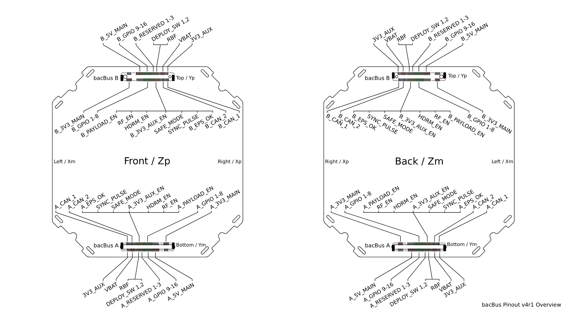
Pinout
Table
| Pin number | Pin name | Type | Bus domain | Notes |
|---|---|---|---|---|
| 1 | CAN_1_H | Differential signal | per bus | Primary CAN bus 1, high |
| 2 | CAN_1_L | Differential signal | per bus | Primary CAN bus 1, low |
| 3, 4 | GND | Ground | shared | Return path |
| 5 | CAN_2_H | Differential signal | per bus | Secondary CAN bus 2, high |
| 6 | CAN_2_L | Differential signal | per bus | Secondary CAN bus 2, low |
| 7, 8 | GND | Ground | shared | Return path |
| 9 | EPS_OK | Flag / status | per bus | Main power rails status flag |
| 10 | SYNC_PULSE | Control / timing | shared | System-wide timestamp sync |
| 11 | SAFE_MODE | Flag / status | shared | System safe-mode control |
| 12 | 3V3_AUX_EN | Control / power | per bus | Auxiliary 3.3V enable |
| 13 | HDRM_EN | Control / inhibit | shared | Hold-down release enable |
| 14 | RF_EN | Control / inhibit | shared | RF subsystem enable |
| 15 | PAYLOAD_EN | Control / payload | per bus | Payload power / enable control |
| 16-23 | GPIO 1-8 | GPIO | per bus | User-defined |
| 24-29 | 3V3_MAIN | Power | per bus | Main 3.3V rail |
| 30-34 | GND | Ground | shared | Return path |
| 35 | 3V3_AUX | Power | shared | Auxiliary 3.3V rail |
| 36-37 | GND | Ground | shared | Return path |
| 38-41 | VBAT | Power | shared | Battery rail, exposed for power and sense |
| 42-43 | GND | Ground | shared | Return path |
| 44 | RBF | Flag / inhibit | shared | High: Remove-before-flight pin removed |
| 45 | DEPLOY_SW_1 | Flag / inhibit | shared | High: Deployment switch group 1 open |
| 46 | DEPLOY_SW_2 | Flag / inhibit | shared | High: Deployment switch group 2 open |
| 47-49 | RESERVED 1-3 | Reserved | per bus | Do not use |
| 50-57 | GPIO 9-16 | GPIO | per bus | User-defined |
| 58-63 | GND | Ground | shared | Return path |
| 64-67 | 5V_MAIN | Power | per bus | Main 5V rail |
Diagram
Reference Files
The following files are provided to simplify hardware design using bacBus.
Pinout definition
Contains the full pin definition including signal descriptions and electrical constraints.
Pin-to-position lookup table
Provides mappings between:
- bacBus pin numbers
- connector pin number
- schematic net names
- hierarchical label names
This simplifies schematic integration and automated symbol generation.
KiKit panel configuration
KiKit configuration for panelizing bacBus interconnect boards.
KiCad Integration
Updated KiCad symbol and footprint presets for bacBus will be provided soon.
These will likely be released alongside the KiCad 10 update.